POWER STEERING SYSTEM TERMINALS OF ECU

-
TERMINALS OF ECU
Tech Tips
The power steering ECU uses waterproof connectors. Therefore, voltage or waveforms cannot be checked with the connectors connected to the vehicle.
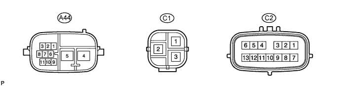
Terminal No. (Symbols) Wiring Color Terminal Description A44-1 (CA2H) R High-level CAN bus line A44-2 (CA1H) B High-level CAN bus line A44-3 (CA1L) W Low-level CAN bus line A44-4 (PIG) B Power source A44-5 (PGND) W-B Power ground A44-6 (+B) R +B A44-7 (WDD1) G DC / DC warning output signal A44-8 (CA2L) G Low-level CAN bus line A44-9 (IG) G IG power source A44-10 (ASST) L DC / DC demand output signal C1-1 (V) W V phase motor output C1-2 (U) B U phase motor output C1-3 (W) R W phase motor output C2-1 (RZG) B Rotation angle sensor power source circuit ground C2-2 (SRZG) BR Rotation angle sensor shield ground C2-3 (RZV) G Rotation angle sensor power source C2-4 (TRQV) W Torque sensor power source C2-6 (TQG1) L-W Torque sensor power source circuit ground C2-7 (RZSN) R SIN phase input signal (rotation angle sensor) C2-8 (RZCS) W COS phase input signal (rotation angle sensor) C2-9 (INSN) G-W SIN phase input signal (torque sensor input shaft side) C2-10 (INCS) R-L COS phase input signal (torque sensor input shaft side) C2-11 (OUSN) G-B SIN phase input signal (torque sensor output shaft side) C2-12 (OUCS) Y-B COS phase input signal (torque sensor output shaft side) C2-13 (TQG2) R-B Torque sensor detection circuit ground -
CHECK WIRE HARNESS SIDE CONNECTOR
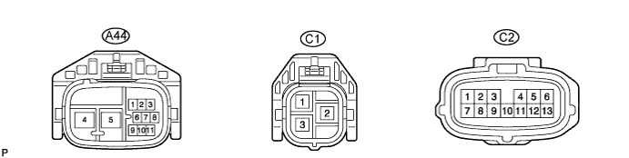
Terminal No.
(Symbols)
Wiring Color Terminal Description Condition Specified Condition A44-4 (PIG) - A44-5 (PGND) B - W-B Power source Power switch ON (READY) 30 to 50 V A44-5 (PGND) - Body ground W-B - Body ground Power ground Always Below 1 Ω A44-9 (IG) - A44-5 (PGND) G - W-B IG power source Power switch ON (IG) 11 to 14 V C1-2 (U) - C1-3 (W)/C1-1 (V) B - R/W U phase motor output Always Below 1 Ω C1-3 (W) - C1-2 (U)/C1-1 (V) R - B/W W phase motor output Always Below 1 Ω C1-1 (V) - C1-2 (U)/ C1-3 (W) W - B/R V phase motor output Always Below 1 Ω