POWER STEERING SYSTEM, Diagnostic DTC:C1552

| DTC Code | DTC Name |
|---|---|
| C1552 | PIG Power Supply Voltage Malfunction |
DESCRIPTION
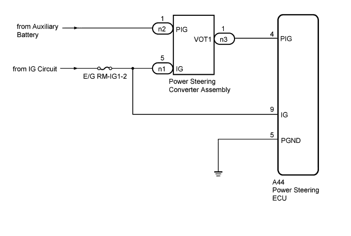
The power steering converter assembly steps down the HV battery voltage to approximately 46 V. This voltage is then supplied to the power steering ECU to operate the motors. As a fail-safe function, when the PIG power supply and power steering converter assembly are malfunctioning, power assistance is stopped.
| DTC Code | Detection Condition | Trouble Area |
|---|---|---|
| C1552 | PIG power supply voltage malfunction |
|
WIRING DIAGRAM
INSPECTION PROCEDURE
PROCEDURE
-
CHECK CONNECTORS
-
Check the connection of the power steering ECU connector.
-
Visually inspect the terminals of the power steering ECU connector.
Result Result Proceed to Normal A Connectors not properly connected B Power steering ECU connector terminals abnormal C Note
If replacing the power steering ECU, initialize the rotation angle sensor value and calibrate the torque sensor zero point Click here.
B 
CONNECT CONNECTORS CORRECTLY
C
REPLACE POWER STEERING ECU Click here
A 
-
-
CHECK POWER STEERING ECU (PIG TERMINAL)
-
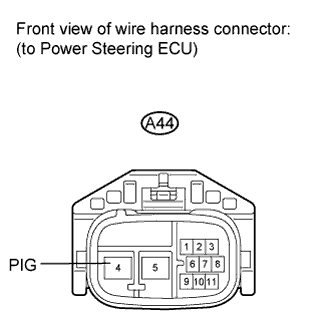
Disconnect the A44 ECU connector.
-
Measure the voltage according to the value(s) in the table below.
Standard voltage Tester Connection Switch Condition Specified Condition A44-4 (PIG) - Body ground Power switch ON (READY) 30 to 48 V Note
If replacing the power steering ECU, initialize the rotation angle sensor value and calibrate the torque sensor zero point Click here.
NG 
CHECK HARNESS AND CONNECTOR (POWER STEERING CONVERTER - BATTERY) Click here
OK 
REPLACE POWER STEERING ECU Click here
-
-
CHECK HARNESS AND CONNECTOR (POWER STEERING CONVERTER - BATTERY)
-
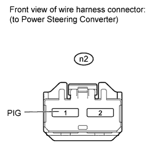
Disconnect the n2 power steering converter connector.
-
Measure the voltage according to the value(s) in the table below.
Standard voltage Tester Connection Condition Specified Condition n2-1 (PIG) - Body ground Always 11 to 14 V
NG
REPAIR OR REPLACE HARNESS OR CONNECTOR
OK
-
-
CHECK HARNESS AND CONNECTOR (POWER STEERING ECU - POWER STEERING CONVERTER AND BODY GROUND)
-
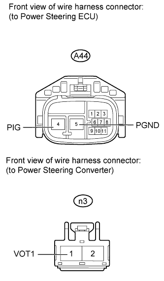
Disconnect the A44 power steering ECU connector.
-
Disconnect the n3 power steering converter connector.
-
Measure the resistance according to the value(s) in the table below.
Standard resistance Tester Connection Condition Specified Condition A44-4 (PIG) - n3-1 (VOT1) Always Below 1 Ω A44-5 (PGND) - Body ground A44-4 (PIG) or n3-1 (VOT1) - Body ground Always 10 kΩ or higher
NG
REPAIR OR REPLACE HARNESS OR CONNECTOR
OK
-
-
CHECK HARNESS AND CONNECTOR (POWER STEERING CONVERTER - BATTERY)
-
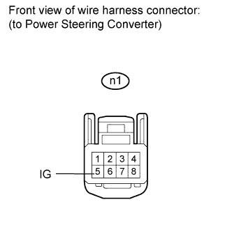
Disconnect the n1 power steering converter connector.
-
Measure the voltage according to the value(s) in the table below.
Standard voltage Tester Connection Switch Condition Specified Condition n1-5 (IG) - Body ground Power switch ON (IG) 11 to 14 V
NG
REPAIR OR REPLACE HARNESS OR CONNECTOR
OK
REPLACE POWER STEERING CONVERTER ASSEMBLY Click here
-