STEERING COLUMN ASSEMBLY INSTALLATION

Tech Tips
-
Use the same procedures for the RHD and LHD.
-
The procedures listed below are for the LHD.
-
INSTALL STEERING COLUMN ASSEMBLY (TILT STEERING GEAR ASSEMBLY WITH MOTOR)
-
Install the steering column assembly with the 4 nuts.
- Torque:
- 26 N*m { 260 kgf*cm, 19 ft.*lbf }
-
Connect the connectors and wire harness clamps to the steering column.
-
-
INSTALL NO. 2 STEERING INTERMEDIATE SHAFT ASSEMBLY
-
Install the clamp to the steering column hole cover sub-assembly.
-
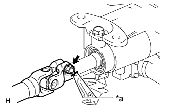
Text in Illustration *a Matchmark Align the matchmarks on the No. 2 steering intermediate shaft assembly and steering column.
-
Install the bolt.
- Torque:
- 35 N*m { 360 kgf*cm, 26 ft.*lbf }
-
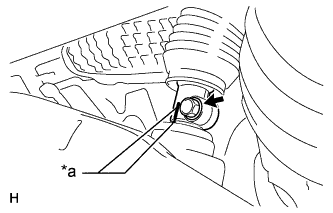
Text in Illustration *a Matchmark Align the matchmarks on the No. 2 steering intermediate shaft assembly and power steering link.
-
Install the bolt.
- Torque:
- 35 N*m { 360 kgf*cm, 26 ft.*lbf }
-
-
PLACE FRONT WHEELS FACING STRAIGHT AHEAD
-
INSTALL NO. 1 AIR DUCT SUB-ASSEMBLY
-
Attach the 2 claws to install the air duct.
-
Install the bolt.
- Torque:
- 9.8 N*m { 100 kgf*cm, 87 in.*lbf }
-
Attach the 2 claws and install the wiring harness protector.
-
-
INSTALL NO. 1 INSTRUMENT PANEL AIRBAG ASSEMBLY LOWER
-
INSTALL TURN SIGNAL SWITCH ASSEMBLY WITH SPIRAL CABLE SUB-ASSEMBLY
-
Install the turn signal switch assembly with spiral cable to the steering column with the clamp.
-
Connect the connectors to the turn signal switch assembly with spiral cable.
-
-
INSTALL STEERING COLUMN COVER (w/o Driver Monitor Camera)
-
Attach the claw to install the upper steering column cover.
-
Attach the 4 clips to install the upper steering column cover onto the instrument cluster finish panel.
-
Attach the 2 claws to install the lower steering column cover.
Note
Do not damage the tilt and telescopic switch.
-
Install the 3 screws.
-
-
INSTALL STEERING COLUMN COVER (w/ Driver Monitor Camera)
-
Connect the driver monitor connector.
-
Attach the claw to install the upper steering column cover.
-
Attach the 4 clips to install the upper steering column cover onto the instrument cluster finish panel.
-
Attach the 2 claws to install the lower steering column cover.
Note
Do not damage the tilt and telescopic switch.
-
Install the 3 screws.
-
-
ADJUST SPIRAL CABLE SUB-ASSEMBLY
Note
Do not adjust the spiral cable sub-assembly with sensor with the auxiliary battery connected and the power switch on (IG).
-
Check that the power switch is off.
-
Check that the cable is disconnected from the negative (-) auxiliary battery terminal.
CAUTION:
Wait at least 90 seconds after disconnecting the cable from the negative (-) auxiliary battery terminal to disable the SRS system.
-
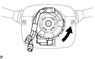
Rotate the spiral cable sub-assembly counterclockwise slowly by hand until it stops.
CAUTION:
Do not turn the spiral cable sub-assembly using the airbag wire harness.
-
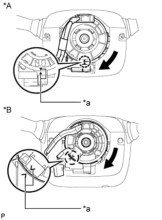
Text in Illustration *A w/o Steering Heater *B w/ Steering Heater *a Alignment Mark Rotate the spiral cable sub-assembly clockwise approximately 2.5 turns to align the marks.
CAUTION:
Do not turn the spiral cable sub-assembly using the airbag wire harness.
Tech Tips
The spiral cable sub-assembly will rotate approximately 2.5 turns to both the left and right from the center.
-
-
INSTALL STEERING WHEEL ASSEMBLY
-
INSPECT STEERING WHEEL CENTER POINT
-
INSPECT STEERING PAD
-
CONNECT CABLE TO AUXILIARY BATTERY NEGATIVE TERMINAL
Note
-
Reset the AUTO TILT AWAY function setting to the previous condition by changing the customize parameter Click here.
-
When disconnecting the cable, some systems need to be initialized after the cable is reconnected Click here.
-
-
INSTALL BATTERY SERVICE HOLE COVER LH
-

Text in Illustration *A for Standard *B for Ottoman Attach the battery service hole cover LH with the clip and fastening tape.
-
-
INSTALL DECK TRIM SIDE BOARD LH (w/o Spare Tire)
-

Attach the 2 clips to install the deck trim side board LH.
-
-
INSTALL DECK BOARD ASSEMBLY (w/o Spare Tire)

-
INSTALL LUGGAGE COMPARTMENT MAT SUB-ASSEMBLY (w/ Spare Tire)

-
CHECK SRS WARNING LIGHT