HEATED STEERING WHEEL SYSTEM Steering Wheel does not Heat Up When Heated Steering Wheel Switch is Pressed
SYSTEM DESCRIPTION
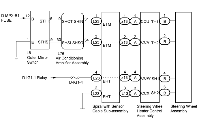
WIRING DIAGRAM
INSPECTION PROCEDURE
Note
Inspect the fuses of this circuit before performing troubleshooting.
PROCEDURE
-
INSPECT STEERING WHEEL ASSEMBLY
-
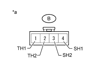
Text in Illustration *a Component without harness connected
(Steering wheel assembly)
Disconnect the B steering wheel assembly connector.
-
Measure the resistance according to the value(s) in the table below.
Standard Resistance Tester Connection Condition Specified Condition B1(TH1) - B2(TH2) 10 to 30°C (50 to 86°F) 8.132 to 18.43 kΩ B4(SH1) - B3(SH2) 20°C (68°F) 1.89 to 2.25 Ω
NG 
REPLACE STEERING WHEEL ASSEMBLY
OK 
-
-
INSPECT SPIRAL CABLE
-
Check the connectors and cables of the spiral with sensor cable sub-assembly.
OK There are no defects such as scratches, cracks, dents or damage on the connectors or cables. -
Disconnect the L23 and z13 spiral with sensor cable subassembly connectors.
-
Measure the resistance according to the value(s) in the table below.
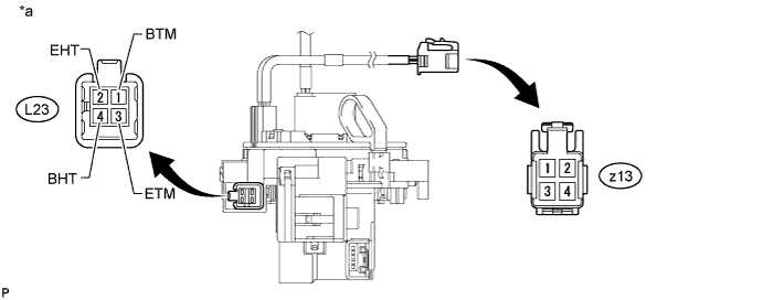
Standard Resistance Tester Connection Condition Specified Condition z13-1 - L23-1(BTM) Always Below 3 Ω z13-2 - L23-3(ETM) Always Below 3 Ω z13-3 - L23-2(EHT) Always Below 0.1 Ω z13-4 - L23-4(BHT) Always Below 0.1 Ω Text in Illustration *a Component without harness connected
(Spiral with Sensor Cable Sub-assembly)
NG
REPLACE SPIRAL CABLE
OK
-
-
INSPECT OUTER MIRROR SWITCH ASSEMBLY
-
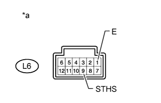
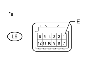
Text in Illustration *a Component without harness connected
Outer Mirror Switch (Steering Heater Switch)
Disconnect the L6 outer mirror switch.
-
Measure the resistance according to the value(s) in the table below.
Standard Resistance Tester Connection Condition Specified Condition L6-1(E) - L6-9(STHS) Outer Mirror Switch (Steering Heater Switch) is pushed Below 1 Ω Outer Mirror Switch (Steering Heater Switch) is not pushed 10 kΩ or higher
NG
REPLACE OUTER MIRROR SWITCH ASSEMBLY
OK
-
-
CHECK HARNESS AND CONNECTOR
-
Disconnect the L6 outer mirror switch.
-
Disconnect the L76 air conditioning amplifier assembly.
-
Measure the resistance according to the value(s) in the table below.
Standard Resistance Tester Connection Condition Specified Condition L6-5(STHI) - L76-9(SHOT) Always Below 1 Ω L6-9(STHS) - L76-30(SHSI) Always Below 1 Ω L6-5(STHI) or L76-9(SHOT) - Body ground Always 10 kΩ or higher L6-9(STHS) or L76-30(SHSI) - Body ground Always 10 kΩ or higher
NG
REPAIR OR REPLACE HARNESS OR CONNECTOR
OK
-
-
CHECK HARNESS AND CONNECTOR
-
Disconnect the L6 outer mirror switch.
-
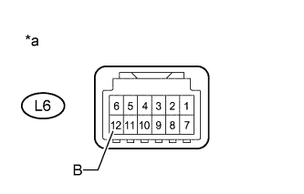
Text in Illustration *a Component without harness connected Measure the voltage according to the value(s) in the table below.
Standard Voltage Tester Connection Condition Specified Condition L6-12(B) - Body ground Power switch on (IG) 11 to 14 V
NG
REPAIR OR REPLACE HARNESS OR CONNECTOR
OK
-
-
CHECK HARNESS AND CONNECTOR
-
Disconnect the L6 outer mirror switch.
-
Text in Illustration *a Component without harness connected Measure the resistance according to the value(s) in the table below.
Standard Resistance Tester Connection Condition Specified Condition L6-1(E) - Body ground Always Below 1 Ω
NG
REPAIR OR REPLACE HARNESS OR CONNECTOR
OK
-
-
CHECK HARNESS AND CONNECTOR
-
Disconnect the L23 spiral with sensor cable subassembly connector.
-
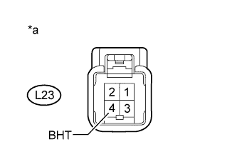
Text in Illustration *a Component without harness connected Measure the voltage according to the value(s) in the table below.
Standard Voltage Tester Connection Condition Specified Condition L23-4(BHT) - Body ground Power switch on (IG) 11 to 14 V
NG
REPAIR OR REPLACE HARNESS OR CONNECTOR
OK
-
-
CHECK HARNESS AND CONNECTOR
-
Disconnect the L76 air conditioning amplifier assembly.
-
Disconnect the L23 spiral with sensor cable subassembly connector.
-
Measure the resistance according to the value(s) in the table below.
Standard Resistance Tester Connection Condition Specified Condition L76-31(SHIN) - L23-1(BTM) Always Below 1 Ω L76-34(SHSO) - L23-3(ETM) Always Below 1 Ω L76-31(SHIN) or L23-1(BTM) - Body ground Always 10 kΩ or higher L76-34(SHSO) or L23-3(ETM) - Body ground Always 10 kΩ or higher
NG
REPAIR OR REPLACE HARNESS OR CONNECTOR
OK
-
-
CHECK HARNESS AND CONNECTOR
-
Disconnect the L23 spiral with sensor cable subassembly connector.
-
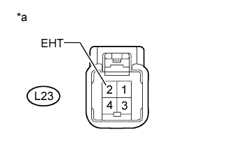
Text in Illustration *a Component without harness connected Measure the resistance according to the value(s) in the table below.
Standard Resistance Tester Connection Condition Specified Condition L23-2(EHT) - Body ground Always Below 1 Ω
NG
REPAIR OR REPLACE HARNESS OR CONNECTOR
OK
-
-
CHECK AIR CONDITIONING AMPLIFIER ASSEMBLY
-
Connect the L76 air conditioning amplifier assembly connector.
-
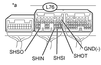
Text in Illustration *a Component with harness connected
(Air conditioning amplifier assembly)
Measure the voltage according to the value(s) in the table below.
Standard Voltage Tester Connection Condition Specified Condition L76-9 (SHOT) - L76-1(GND) Power switch on (IG)
Outer Mirror Switch (Steering Heater Switch) OFF
11 to 14 V Power switch on (IG)
Outer Mirror Switch (Steering Heater Switch) ON
Below 1 V L76-30 (SHSI) - L76-1(GND) Power switch on (IG)
Outer Mirror Switch (Steering Heater Switch) OFF
4.75 to 5.25 V Power switch on (IG)
Outer Mirror Switch (Steering Heater Switch) ON
Below 1 V L76-31 (SHIN) - L76-1(GND) Power switch on (IG)
Outer Mirror Switch (Steering Heater Switch) OFF
4.75 to 5.25 V Power switch on (IG)
Outer Mirror Switch (Steering Heater Switch) ON
Below 1 V L76-34 (SHSO) - L76-1(GND) Power switch on (IG)
Outer Mirror Switch (Steering Heater Switch) OFF
Below 1 V Power switch on (IG)
Outer Mirror Switch (Steering Heater Switch) ON
11 to 14 V
NG
REPLACE AIR CONDITIONING AMPLIFIER ASSEMBLY
OK 
REPLACE STEERING WHEEL HEATER CONTROL ASSEMBLY
-