VARIABLE GEAR RATIO STEERING SYSTEM VGRS System Stops or does not Operate
INSPECTION PROCEDURE
Tech Tips
This problem may be caused by a malfunction in the electronically controlled brake system or power steering system.
Make sure that no DTC is output for the skid control ECU, power steering ECU, or steering control ECU before proceeding with the following procedures.
If a DTC is output for any of these ECUs, first troubleshoot it and then proceed to the troubleshooting below.
PROCEDURE
-
READ VALUE USING INTELLIGENT TESTER (RECORD OF OVERHEAT)
-
Use the Data List to check if the record of overheat is functioning properly.
VGRS: Tester Display Measurement Item/Range Normal Condition Diagnostic Note Motor Overheat Record Record of continuous overheat preventive control / Rec or Unrec Rec or Unrec - Result Result Proceed to "Rec" (Record of motor overheating) A "Unrec" (No record of motor overheating) B Tech Tips
If "Rec" is displayed, reset the setting to "Unrec". Enter the VGRS menu on the tester, select record clearance, and follow the prompts to set to "Unrec".
B 
CHECK STEERING EFFORT Click here
A 
-
-
CHECK HEAT PROTECTION FUNCTION FOR STEERING ACTUATOR
-
Turn the power switch ON (IG) and wait for 30 minutes until the steering actuator cools down.
-
Turn the power switch ON (READY) and slowly turn the steering wheel from lock to lock (approximately 90°/sec) 3 times.
Tech Tips
If turning the steering wheel quickly while driving at low speeds, the steering angle may differ between the left and right, or the steering wheel may become off-center.
However, this is not a malfunction.
-
Check the number of turns from lock to lock.
Result Result Proceed to 3.2 turns A 2.7 turns B
B 
VGRS SYSTEM IS NORMAL
A
-
-
CHECK STEERING EFFORT
-
Turn the power switch ON (READY).
-
Turn the steering wheel.
-
Measure the steering effort.
Standard steering effort Below 6.9 N*m (70 kgf*cm, 61 in.*lbf) Tech Tips
After completing the inspection or repair, attempt to simulate the problem and then perform "READ VALUE OF INTELLIGENT TESTER" above again to reconfirm that the problem does not occur.
NG
GO TO POWER STEERING SYSTEM (HOW TO PROCEED WITH TROUBLESHOOTING) Click here
OK
-
-
CHECK STEERING ACTUATOR
-
Check for abnormal noise or vibration in the steering actuator.
OK Neither abnormal noise nor vibration occurs.
NG
GO TO STEERING WHEEL VIBRATES OR ABNORMAL NOISE IS HEARD FROM STEERING WHEEL Click here
OK
-
-
CHECK STEERING CONTROL ECU (POWER SOURCE CIRCUIT)
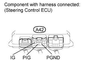
-
Measure the voltage according to the value(s) in the table below.
Standard voltage Tester Connection Switch Condition Specified Condition A42-3 (IG) -
Body ground
Power switch ON (IG) 11 to 14 V A42-8 (PIG) -
Body ground
-
Turn the power switch OFF.
-
Measure the resistance according to the value(s) in the table below.
Standard resistance Tester Connection Condition Specified Condition A42-7 (PGND) -
Body ground
Always Below 1 Ω
NG
REPAIR OR REPLACE HARNESS OR CONNECTOR
OK 
REPLACE STEERING CONTROL ECU Click here
-