VARIABLE GEAR RATIO STEERING SYSTEM TERMINALS OF ECU

-
CHECK STEERING CONTROL ECU
Tech Tips
Inspect the connectors from the back side while they are connected.
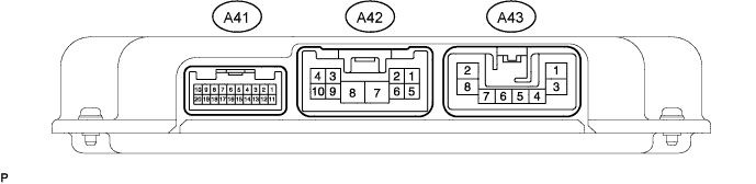
Terminal No. (Symbols) Wiring Color Terminal Description Condition Specified Condition A42-3 (IG) - A42-7 (PGND) P - W-B Power supply (P-IG1-3 fuse) Power switch ON (IG) 11 to 14 V A42-4 (CAN+) - A42-9 (CAN-) Y - L CAN communication Power switch ON (IG) Pulse generation A42-7 (PGND) - Body ground W-B - Body ground Ground Always Below 1 Ω A42-8 (PIG) - A42-7 (PGND) L - W-B Power supply (VGRS fuse) Power switch ON (IG) 11 to 14 V A42-10 (+BI) - A42-7 (PGND) R - W-B Power supply (P MPX-B fuse) Always 11 to 14 V A43-1 (BMV) - A42-7 (PGND) W - W-B Steering actuator motor signal (V phase) Power switch ON (READY) Sine wave A43-2 (BMU) - A42-7 (PGND) B - W-B Steering actuator motor signal (U phase) Power switch ON (READY) Sine wave A43-3 (BMW) - A42-7 (PGND) L - W-B Steering actuator motor signal (W phase) Power switch ON (READY) Sine wave A43-6 (SG) - A43-8 (PGD2) BR - W-B Steering actuator motor signal shield ground Always Below 1 Ω A43-8 (PGD2) - Body ground W-B - Body ground Steering control ECU ground Always Below 1 Ω A41-1 (+BO) - A42-7 (PGND) R - W-B Steering sensor power supply line Always 11 to 14 V A41-3 (LV) - A42-7 (PGND) Y - W-B Power source for steering actuator lock Power switch ON (IG) 11 to 14 V A41-4 (S1) - A42-7 (PGND) W - W-B Steering actuator motor rotation angle sensor signal Power switch ON (IG) Sine wave A41-6 (RV) - A42-7 (PGND) B - W-B Steering actuator resolver excitation output voltage Power switch ON (IG) Sine wave A41-7 (SIL) - A42-7 (PGND) V - W-B Diagnostic communication signal Power switch ON (IG) Pulse generation A41-9 (CANH) - A41-20 (CANL) B - W CAN communication Power switch ON (IG) Pulse generation A41-10 (SS1-) - A42-7 (PGND) LG - W-B Steering angle sensor signal Power switch ON (READY), steering wheel is turned Pulse generation A41-12 (LG) - A42-7 (PGND) L - W-B Steering actuator lock ground Power switch ON (READY) Pulse generation A41-14 (S2) - A42-7 (PGND) R - W-B Steering actuator motor rotation angle sensor signal Power switch ON (IG) Sine wave A41-15 (RG) - A42-7 (PGND) G - W-B Steering actuator resolver common ground Always Below 1 Ω A41-16 (SG2+) - A42-7 (PGND) Shielded - W-B Ground for steering actuator motor rotation angle sensor signal wire and control signal wire shield wire Power switch ON (IG) Pulse generation A41-19 (SS1+) - A42-7 (PGND) L - W-B Steering angle sensor signal Power switch ON (READY), steering wheel is turned 3 to 4 V