STEERING LOCK SYSTEM Power Source Circuit
DESCRIPTION
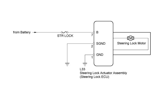
This circuit supplies power source voltage from the battery to terminal B of the steering lock ECU.
The diagnosis information of the steering lock ECU is transmitted to the tester via the certification ECU as the steering lock ECU is not connected to the CAN communication system.
WIRING DIAGRAM
INSPECTION PROCEDURE
Tech Tips
When the power switch is OFF, the main body ECU may occasionally go into a non-active state called sleep mode. Therefore, before proceeding with the inspection, it is necessary to perform the following steps to wake up the ECU:
With the power switch OFF, open the driver door. Then (with the power switch still OFF) open and close any door several times at 1.5 second intervals.
PROCEDURE
-
INSPECT FUSE (STR LOCK)
-
Remove the STR LOCK fuse from the main body ECU.
-
Measure the resistance according to the value(s) in the table below.
Standard resistance Tester Connection Condition Specified Condition STR LOCK fuse Always Below 1 Ω
NG 
REPLACE FUSE
OK 
-
-
CHECK HARNESS AND CONNECTOR (STEERING LOCK ECU - BATTERY)
-
Disconnect the L33 steering lock ECU connector.
-
Measure the voltage according to the value(s) in the table below.
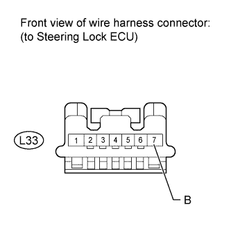
Standard voltage Tester Connection Condition Specified Condition L33-7 (B) - Body ground Always 11 to 14 V
NG
REPAIR OR REPLACE HARNESS OR CONNECTOR
OK
-
-
CHECK HARNESS AND CONNECTOR (STEERING LOCK ECU - BODY GROUND)
-
Disconnect the L33 steering lock ECU connector.
-
Measure the resistance according to the value(s) in the table below.
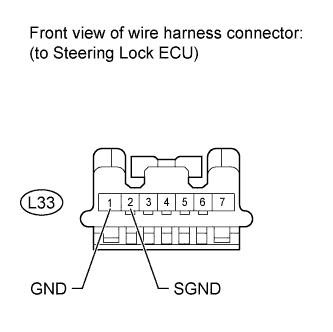
Standard resistance Tester Connection Condition Specified Condition L33-1 (GND) - Body ground Always Below 1 Ω L33-2 (SGND) - Body ground Always Below 1 Ω
NG
REPAIR OR REPLACE HARNESS OR CONNECTOR
OK 
GO TO STEERING LOCK SYSTEM (PROBLEM SYMPTOMS TABLE) Click here
-