VARIABLE GEAR RATIO STEERING SYSTEM, Diagnostic DTC:C15A5/65

| DTC Code | DTC Name |
|---|---|
| C15A5/65 | Actuator Malfunction |
DESCRIPTION
If the steering control ECU detects a malfunction in the lock mechanism, it will turn the master warning light on, store the DTC C15A5/65, and stop VGRS operation.
| DTC Code | Detection Condition | Trouble Area |
|---|---|---|
| C15A5/65 | The steering control ECU detects that the LG terminal voltage is abnormal |
|
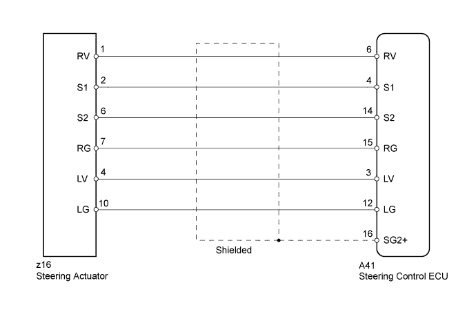
WIRING DIAGRAM
INSPECTION PROCEDURE
PROCEDURE
-
CHECK HARNESS AND CONNECTOR (STEERING CONTROL ECU - STEERING ACTUATOR)
-
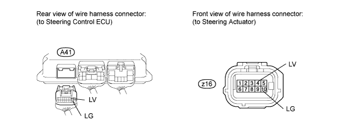
Disconnect the A41 steering control ECU connector.
-
Disconnect the z16 steering actuator connector.
-
Measure the resistance according to the value(s) in the table below.
Standard resistance Tester Connection Condition Specified Condition A41-3 (LV) - z16-4 (LV) Always Below 1 Ω A41-12 (LG) - z16-10 (LG) A41-3 (LV) - Body ground Always 10 kΩ or higher A41-12 (LG) - Body ground -
Measure the voltage according to the value(s) in the table below.
Standard voltage Tester Connection Switch Condition Specified Condition A41-3 (LV) - Body ground Power switch ON (IG) Below 1 V A41-12 (LG) - Body ground
NG 
REPAIR OR REPLACE HARNESS OR CONNECTOR
OK 
-
-
CHECK HARNESS AND CONNECTOR (STEERING CONTROL ECU - STEERING ACTUATOR)
-
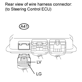
Disconnect the A41 steering control ECU connector.
-
Reconnect the z16 steering actuator connector.
-
Measure the resistance according to the value(s) in the table below.
Standard resistance Tester Connection Condition Specified Condition A41-3 (LV) - A41-12 (LG) Always 10 to 100 Ω A41-3 (LV) - Body ground Always 10 kΩ or higher A41-12 (LG) - Body ground
NG
REPLACE STEERING ACTUATOR Click here
OK 
REPLACE STEERING CONTROL ECU Click here
-