ELECTRIC PARKING BRAKE SWITCH REMOVAL

Tech Tips
-
Use the same procedures for the RHD and LHD.
-
The procedures listed below are for the LHD.
-
REMOVE INSTRUMENT SIDE PANEL LH (for LHD)
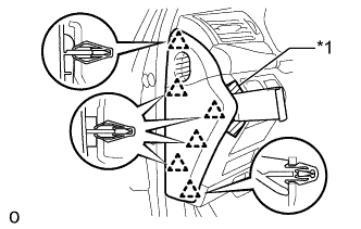
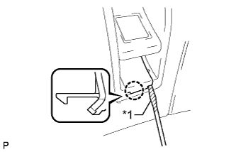
Text in Illustration *1 Protective Tape
-
Apply protective tape as shown in the illustration.
-
Using moulding remover D, detach the 6 clips and remove the instrument side panel LH.
-
-
REMOVE INSTRUMENT SIDE PANEL RH (for RHD)
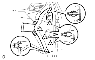
Text in Illustration *1 Protective Tape
-
Apply protective tape as shown in the illustration.
-
Using moulding remover D, detach the 6 clips and remove the instrument side panel RH.
-
-
REMOVE INSTRUMENT PANEL ORNAMENT
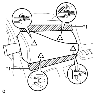
Text in Illustration *1 Protective Tape
-
Apply protective tape as shown in the illustration.
-
Using moulding remover B, detach the 4 clips and remove the instrument panel ornament.
-
Disconnect the connector.
-
-
REMOVE SWITCH BASE HOLE COVER
-
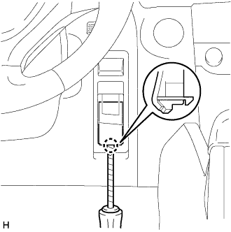
Using a screwdriver, detach the claw and remove the cover from the No. 1 instrument panel safety pad.
Tech Tips
Tape the screwdriver tip before use.
-
Remove the screw.
-
-
REMOVE NO. 1 INSTRUMENT PANEL SAFETY PAD SUB-ASSEMBLY
-
Text in Illustration *1 Protective Tape Using a screwdriver, detach the claw and remove the switch base hole cover from the No. 1 instrument panel safety pad sub-assembly.
Tech Tips
Tape the screwdriver tip before use.
-
Remove the bolt.
-
Remove the screw <C>.
-
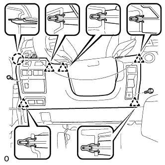
Detach the 5 clips and claw and remove the No. 1 instrument panel safety pad sub-assembly.
-
Disconnect each connector.
-
-
REMOVE ELECTRIC PARKING BRAKE SWITCH ASSEMBLY
-
Disconnect the connector.
-
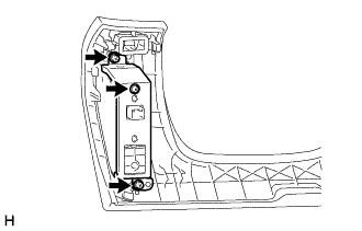
Remove the 3 screws and bracket from the No. 1 instrument panel safety pad.
-
Remove the electric parking brake switch from the No. 1 instrument panel safety pad.
-