ELECTRIC PARKING BRAKE SYSTEM, Diagnostic DTC:C13A8/44

| DTC Code | DTC Name |
|---|---|
| C13A8/44 | Tension Sensor Malfunction |
DESCRIPTION
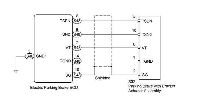
The tension sensor is built into the parking brake with bracket actuator assembly. It detects the tension value of the parking brake cable and outputs the value to the electric parking brake ECU.
| DTC Code | Detection Condition | Trouble Area |
|---|---|---|
| C13A8/44 | All of following conditions are met:
|
|
WIRING DIAGRAM
INSPECTION PROCEDURE
Note
-
If the electric parking brake ECU or parking brake with bracket actuator assembly is replaced, perform the "RESET MEMORY" and "ACQUIRE TENSION SENSOR ZERO POINT" procedures Click here.
-
Even after the power switch is turned OFF, the electric parking brake ECU may store a DTC as a result of removing a connector or fuse, as the ECU is still operating. Therefore, during inspection or replacement, turn the power switch OFF and wait for 20 seconds before removing the following: 1) connectors of the electric parking brake ECU, and 2) fuses of the electric parking brake system circuit.
-
This DTC may be output if a manual release cable is used. There is no malfunction. Perform the "RESET MEMORY" and "ACQUIRE TENSION SENSOR ZERO POINT" procedures Click here.
PROCEDURE
-
CLEAR DTC
-
Turn the power switch OFF.
-
Connect the intelligent tester to the DLC3.
-
Turn the power switch ON (IG) and the tester ON.
-
Clear the DTC Click here.
NEXT 
-
-
CHECK DTC
-
Turn the power switch OFF.
-
Connect the intelligent tester to the DLC3.
-
Turn the power switch ON (IG) and the tester ON.
-
Check for DTC Click here.
Result Result Proceed to DTC is output A DTC is not output B
B 
USE SIMULATION METHOD TO CHECK Click here
A
-
-
CHECK HARNESS AND CONNECTOR (ECU - ACTUATOR)
-
Disconnect the S48 ECU connector.
-
Disconnect the S32 actuator connector.
-
Measure the resistance according to the value(s) in the table below.
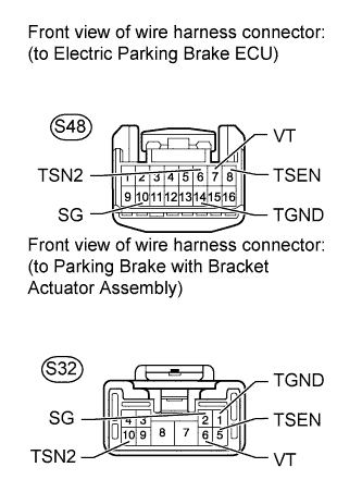
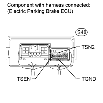
Standard resistance Tester Connection Condition Specified Condition S48-8 (TSEN) - S32-5 (TSEN) Always Below 1 Ω S48-8 (TSEN) - Body ground Always 10 kΩ or higher S48-6 (TSN2) - S32-10 (TSN2) Always Below 1 Ω S48-6 (TSN2) - Body ground Always 10 kΩ or higher S48-7 (VT) - S32-6 (VT) Always Below 1 Ω S48-7 (VT) - Body ground Always 10 kΩ or higher S48-14 (TGND) - S32-1 (TGND) Always Below 1 Ω S48-14 (TGND) - Body ground Always 10 kΩ or higher S48-10 (SG) - S32-2 (SG) Always Below 1 Ω S48-10 (SG) - Body ground Always 10 kΩ or higher
NG
REPAIR OR REPLACE HARNESS OR CONNECTOR
OK
-
-
CHECK ELECTRIC PARKING BRAKE ECU (VT VOLTAGE)
-
Measure the voltage according to the value(s) in the table below.
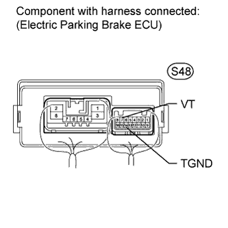
Standard voltage Tester Connection Switch Condition Specified Condition S48-7 (VT) - S48-14 (TGND) Power switch ON (IG) 4.75 to 5.25 V Result Result Proceed to Outside of the specified condition A Within the specified condition B
B 
CHECK ELECTRIC PARKING BRAKE ECU (TSEN, TSN2, TGND) Click here
A
-
-
CHECK ELECTRIC PARKING BRAKE ECU (VT VOLTAGE)
-
Disconnect the S32 actuator connector.
-
Measure the voltage according to the value(s) in the table below.
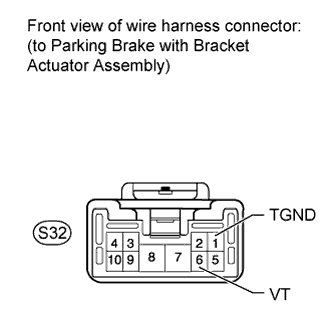
Standard voltage Tester Connection Condition Specified Condition S32-6 (VT) - S32-1 (TGND) Power switch ON (IG) 4.75 to 5.25 V
NG
REPLACE ELECTRIC PARKING BRAKE ECU Click here
OK 
REPLACE PARKING BRAKE WITH BRACKET ACTUATOR ASSEMBLY Click here
-
-
CHECK ELECTRIC PARKING BRAKE ECU (TSEN, TSN2, TGND)
-
Connect the S48 ECU connector.
-
Connect the S32 actuator connector.
-
Measure the voltage between the terminals below.
Measurement condition Tester Connection Switch Condition (A) S48-6 (TSN2) - S48-14 (TGND) Power switch ON (IG) (B) S48-8 (TSEN) - S48-14 (TGND) Power switch ON (IG) Tech Tips
Take a note of the measurements.
-
Turn the power switch OFF.
-
Connect the intelligent tester to the DLC3.
-
Turn the power switch ON (IG) and the tester ON.
-
Enter the following menus: Chassis / Electric Parking Brake / Data List.
-
Check the values by referring to the table below.
Tech Tips
This procedure is performed to compare the difference between the actual voltage and the voltage recognized by the ECU.
Electric Parking Brake Tester Display Measurement Item/Range Normal Condition Diagnostic Note (1) Tension1 Voltage Tension sensor 1 voltage display/
min.: 0.000 V
max.: 5.000 V
Voltage (A) +/-0.2 V is 0.3 to 4.7 V - (2) Tension2 Voltage Tension sensor 2 voltage display/
min.: 0.000 V
max.: 5.000 V
Voltage (B) +/-0.2 V is 0.3 to 4.7 V - (3) Invalid Tension Sensor Comp Tension sensor comparison invalid display/
Enable or Disable
Enable - OK Values are as shown in normal condition. Result Result Proceed to (1), (2) or (3) are NG A (1), (2) and (3) are OK B
B
CHECK ELECTRIC PARKING BRAKE ECU (DATA LIST) Click here
A
-
-
INSPECT ELECTRIC PARKING BRAKE ECU
-
Remove the electric parking brake ECU Click here.
-
Measure the resistance according to the value(s) in the table below.
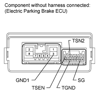
Standard resistance Tester Connection Condition Specified Condition 8 (TSEN) - 3 (GND1) Always 4 to 6 kΩ 6 (TSN2) - 3 (GND1) Always 4 to 6 kΩ 14 (TGND) - 3 (GND1) Always Below 1 Ω 10 (SG) - 3 (GND1) Always Below 1 Ω
NG
REPLACE ELECTRIC PARKING BRAKE ECU Click here
OK
REPLACE PARKING BRAKE WITH BRACKET ACTUATOR ASSEMBLY Click here
-
-
CHECK ELECTRIC PARKING BRAKE ECU (DATA LIST)
-
Turn the power switch OFF.
-
Connect the intelligent tester to the DLC3.
-
Turn the power switch ON (IG) and the tester ON.
-
Enter the following menus: Chassis / Electric Parking Brake / Data List.
-
Check the values by referring to the table below.
Electric Parking Brake Tester Display Measurement Item/Range Normal Condition Diagnostic Note Invalid Tension Sensor Output Tension sensor output invalid display/
Enable or Disable
Enable - Invalid Tension Sensor PWR Tension sensor power source invalid display/
Enable or Disable
Enable - Invalid Tension Sensor Comp Tension sensor comparison invalid display/
Enable or Disable
Enable - +B Voltage Value +B power source information display/
Lo / Mid / Hi
Hi - OK Values are as shown in normal condition.
NG
REPLACE ELECTRIC PARKING BRAKE ECU Click here
OK
USE SIMULATION METHOD TO CHECK Click here
-