ELECTRIC PARKING BRAKE SYSTEM, Diagnostic DTC:C13A1/12

| DTC Code | DTC Name |
|---|---|
| C13A1/12 | Short in Power Supply Relay Circuit |
DESCRIPTION
The electric parking brake ECU performs the lock/release operation of the parking brake based on signals from the electric parking brake switch, or instruction signals from other systems via CAN communication.
| DTC Code | Detection Condition | Trouble Area |
|---|---|---|
| C13A1/12 | Both of following conditions are met:
|
|
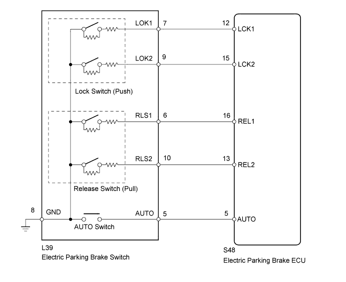
WIRING DIAGRAM
INSPECTION PROCEDURE
Note
-
If the electric parking brake ECU or parking brake with bracket actuator assembly is replaced, perform the "RESET MEMORY" and "ACQUIRE TENSION SENSOR ZERO POINT" procedures Click here.
-
Even after the power switch is turned OFF, the electric parking brake ECU may store a DTC as a result of removing a connector or fuse, as the ECU is still operating. Therefore, during inspection or replacement, turn the power switch OFF and wait for 20 seconds before removing the following: 1) connectors of the electric parking brake ECU, and 2) fuses of the electric parking brake system circuit.
PROCEDURE
-
INSPECT ELECTRIC PARKING BRAKE SWITCH
-
Remove the electric parking brake switch Click here.
-
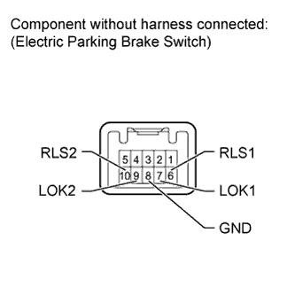
Measure the resistance according to the value(s) in the table below.
Standard resistance Tester Connection Switch Condition Specified Condition 6 (RLS1) - 8 (GND) OFF 5.51 to 6.09 kΩ 7 (LOK1) - 8 (GND) OFF 97.09 to 107.31 kΩ 9 (LOK2) - 8 (GND) OFF 5.51 to 6.09 kΩ 10 (RLS2) - 8 (GND) OFF 5.51 to 6.09 kΩ
NG 
REPLACE ELECTRIC PARKING BRAKE SWITCH Click here
OK 
-
-
CHECK HARNESS AND CONNECTOR (ECU - SWITCH)
-
Disconnect the L39 switch connector.
-
Disconnect the S48 ECU connector.
-
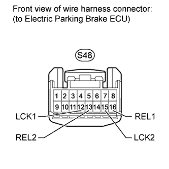
Measure the resistance according to the value(s) in the table below.
Standard resistance Tester Connection Condition Specified Condition S48-12 (LCK1) - Body ground Always 10 kΩ or higher S48-13 (REL2) - Body ground Always 10 kΩ or higher S48-15 (LCK2) - Body ground Always 10 kΩ or higher S48-16 (REL1) - Body ground Always 10 kΩ or higher
NG
REPAIR OR REPLACE HARNESS OR CONNECTOR
OK 
REPLACE ELECTRIC PARKING BRAKE ECU Click here
-