REAR BRAKE REMOVAL

Tech Tips
-
Use the same procedures for the LH side and RH side.
-
The procedures listed below are for the LH side.
Note
While the battery is connected, even if the power switch is off, the brake control system activates when the brake pedal is depressed or the door courtesy switch turns on. Therefore during servicing of the brake system components, do not operate the brake pedal or open/close the doors while the battery is connected.
-
REMOVE LUGGAGE COMPARTMENT MAT SUB-ASSEMBLY (w/ Spare Tire)

-
REMOVE DECK BOARD ASSEMBLY (w/o Spare Tire)

-
REMOVE DECK TRIM SIDE BOARD LH (w/o Spare Tire)
-

Detach the 2 clips and remove the deck trim side board LH.
-
-
REMOVE BATTERY SERVICE HOLE COVER LH
-

Text in Illustration *A for Standard *B for Ottoman *1 Fastening Tape Detach the clip, fastening tape and remove the battery service hole cover LH.
-
-
PRECAUTION
Note
After turning the power switch off, waiting time may be required before disconnecting the cable from the auxiliary battery terminal. Therefore, make sure to read the disconnecting the cable from the auxiliary battery terminal notice before proceeding with work Click here.
-
DISCONNECT CABLE FROM AUXILIARY BATTERY NEGATIVE TERMINAL
Note
When disconnecting the cable, some systems need to be initialized after the cable is reconnected Click here.
-
REMOVE REAR WHEEL
-
REMOVE REAR DISC BRAKE PAD KIT
-
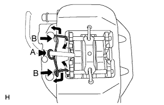
While pressing the area labeled A, push the hole pins (labeled B) toward the brake caliper, and remove the pin hold clip.
Note
The pin hold clip can be used again if it has sufficient rebound; no deformation or wear; and has had all rust, dirt and foreign particles cleaned off.
-
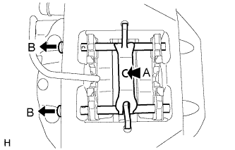
While pressing the area labeled A, remove the 2 rear disc brake anti-rattles with hole pins (labeled B).
-
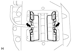
Remove the rear disc brake anti-rattle spring.
Note
The anti-rattle spring can be used again if it has sufficient rebound; no deformation, cracks or wear; and has had all rust, dirt and foreign particles cleaned off.
-
Remove the 2 pads from the disc brake caliper.
-
Remove the 2 anti-squeal shims and anti-rattle spring from each pad.
-
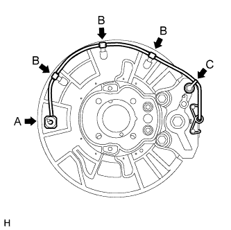
Disconnect the pad wear indicator wire connector (labeled A).
-
Detach the 3 clamps (labeled B) and bleeder plug cap (labeled C).
-
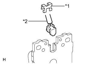
Text in Illustration *1 Retainer *2 Pad Wear Indicator Wire Remove the retainer and pad wear indicator wire from the inner pad.
-
-
DRAIN BRAKE FLUID
Note
Wash brake fluid off immediately if it is spilled on any painted surface.
-
DISCONNECT REAR BRAKE FLEXIBLE HOSE
-
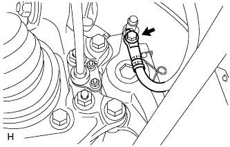
Remove the union bolt and gasket from the disc brake caliper, and then disconnect the flexible hose.
-
-
REMOVE REAR DISC BRAKE CALIPER ASSEMBLY LH
-
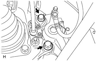
Remove the 2 bolts and disc brake caliper from the knuckle.
-
-
REMOVE PARKING BRAKE SHOE ADJUSTING HOLE PLUG
-
REMOVE REAR DISC
-
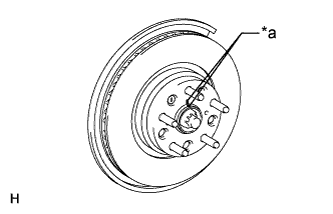
Text in Illustration *a Matchmark Put matchmarks on the rear disc and axle hub if planning to reuse the disc.
-
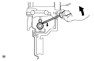
Turn the shoe adjuster until the disc turns freely, and then remove the disc.
-