FRONT BRAKE (except 6-Pot Caliper) INSTALLATION

Tech Tips
-
Use the same procedures for the LH side and RH side.
-
The procedures listed below are for the LH side.
Note
While the battery is connected, even if the power switch is off, the brake control system activates when the brake pedal is depressed or the door courtesy switch turns on. Therefore during servicing of the brake system components, do not operate the brake pedal or open/close the doors while the battery is connected.
-
INSTALL FRONT DISC
Note
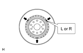
The disc has an identification mark. Make sure of the identification mark when installing the disc.
Item Identification Mark LH L RH R
-
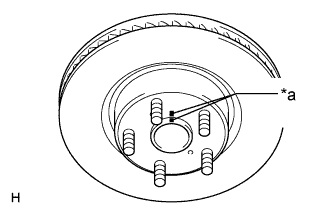
Text in Illustration *a Matchmark Align the matchmarks, and install the front disc.
Tech Tips
When replacing the front disc with a new one, select the installation position where the front disc has the minimum runout.
-
-
INSTALL FRONT DISC BRAKE CALIPER ASSEMBLY LH
-
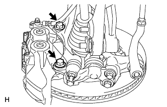
Install the disc brake caliper with 2 new bolts.
- Torque:
- 135 N*m { 1377 kgf*cm, 100 ft.*lbf }
-
-
CONNECT FRONT BRAKE FLEXIBLE HOSE
-
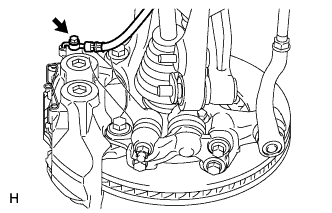
Connect the flexible hose with a new union bolt and a new gasket.
- Torque:
- 39 N*m { 400 kgf*cm, 29 ft.*lbf }
Note
Install the flexible hose lock securely in the lock hole in the disc brake caliper.
-
-
INSTALL FRONT DISC BRAKE PAD KIT
Note
-
When replacing worn pads, the anti-squeal shims must be replaced together with the pad.
-
When installing the shim, make sure its arrow is pointing in the direction of disc rotation for forward movement.
-
Install each shim in the correct position and direction.
-
Install each pad as shown in the illustration below.
-
There should be no oil or grease on the friction surface of the pads and the disc.
-
When replacing the brake pad on ECB (Electronically Controlled Brake) system equipped vehicles, retracting the caliper's piston and attaching a new brake pad will greatly increase the clearance between the brake pad and disc rotor, which will likely cause a DTC(s) to be set the next time the brake pedal is pressed.
As there is no malfunction, delete the DTC(s).
Refer to the following DTC chart for details on which DTC(s) to delete if DTC(s) is set.
DTC Meaning of DTC C1341 Front Hydraulic System RH malfunction C1342 Front Hydraulic System LH malfunction
-
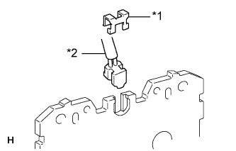
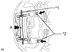
Text in Illustration *1 Retainer *2 Pad Wear Indicator Wire Install the pad wear indicator wire and a new retainer to the inner pad.
-
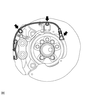
Attach the clamp and bleeder plug cap.
-
Connect the pad wear indicator wire connector.
-
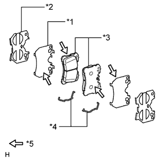
Text in Illustration *1 No. 1 Anti-squeal Shim *2 No. 2 Anti-squeal Shim *3 Disc Brake Pad *4 Anti-rattle Spring *5 Disc brake grease Install the anti-rattle spring to each pad.
Tech Tips
Install the spring lock securely in the groove of the pad.
-
Apply disc brake grease to the sides of the 2 No. 1 anti-squeal shims that contact the disc brake pad.
Note
Do not apply grease to the sides of the 2 No. 1 anti-squeal shims that contact the No. 2 anti-squeal shims.
-
Install the No. 1 and No. 2 anti-squeal shims to each pad.
-
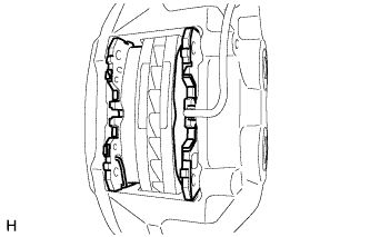
Install the 2 pads to the disc brake caliper.
-
Install the front disc brake anti-rattle spring between the 2 pads.
Note
The anti-rattle spring can be used again if it has sufficient rebound; no deformation, cracks or wear; and has had all rust, dirt and foreign particles cleaned off.
-
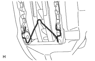
Text in Illustration *1 Anti-rattle Spring *2 Hole Pin Install the front disc brake anti-rattle spring to the disc brake caliper.
Note
The anti-rattle spring can be used again if it has sufficient rebound; no deformation, cracks or wear; and has had all rust, dirt and foreign particles cleaned off.
-
While pressing the area labeled A, install the 2 front disc brake anti-rattles with hole pins.
-
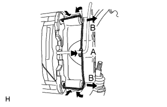
While pressing the area labeled A, slightly pull out the hole pins (labeled B) from the brake caliper, and install the pin hold clip.
Note
The pin hold clip can be used again if it has sufficient rebound; no deformation or wear; and has had all rust, dirt and foreign particles cleaned off.
-
-
CONNECT CABLE TO AUXILIARY BATTERY NEGATIVE TERMINAL
Note
When disconnecting the cable, some systems need to be initialized after the cable is reconnected Click here.
-
INSTALL BATTERY SERVICE HOLE COVER LH
-

Text in Illustration *A for Standard *B for Ottoman Attach the battery service hole cover LH with the clip and fastening tape.
-
-
INSTALL DECK TRIM SIDE BOARD LH (w/o Spare Tire)
-

Attach the 2 clips to install the deck trim side board LH.
-
-
INSTALL DECK BOARD ASSEMBLY (w/o Spare Tire)

-
INSTALL LUGGAGE COMPARTMENT MAT SUB-ASSEMBLY (w/ Spare Tire)

-
BLEED BRAKE LINE
-
Bleed brake line.
-
Remove the brake master cylinder reservoir filler cap assembly.
-
Add brake fluid into the reservoir between MAX and MIN level on the brake fluid reservoir.
Brake fluid SAE J1703 or FMVSS No. 116 DOT3 -
Connect the intelligent tester to the DLC3 and turn the power switch on (IG).
-
Turn the intelligent tester on and enter the following menus: Chassis / ABS/VSC/TRC / Utility / Air Bleeding.
-
Select the "Usual air bleeding / All Line" and bleed brake line according to the intelligent tester display.
-
After air bleeding, tighten each bleeder plug.
- Torque:
- for Front Brake (except 6-pot caliper)
- 11 N*m { 110 kgf*cm, 8 ft.*lbf }
- for Front Brake (6-pot caliper)
- 19 N*m { 194 kgf*cm, 14 ft.*lbf }
- for Rear Brake
- 11 N*m { 110 kgf*cm, 8 ft.*lbf }
-
-
Clear the DTCs Click here.
-
Turn the intelligent tester off and turn the power switch off.
-
Inspect for brake fluid leaks.
-
Adjust the brake fluid level in the reservoir Click here.
-
-
INSTALL FRONT WHEEL
- Torque:
- 140 N*m { 1428 kgf*cm, 103 ft.*lbf }
-
CLEAR THE DTC
-
CHECK FOR DTC
-
Check for DTC. If any DTC is output, perform the troubleshooting for that DTC Click here.
-