FRONT BRAKE (for 6-Pot Caliper) INSTALLATION

-
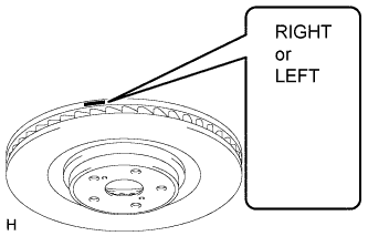
INSTALL FRONT DISC
Note
Be sure to check the identification mark when installing the disc.
Item Identification mark LH LEFT RH RIGHT
-
Align the matchmarks and install the front disc.
Note
When replacing the front disc with a new one, select the installation position where the front disc has minimum runout.
-
-
INSTALL FRONT DISC BRAKE CYLINDER ASSEMBLY
-
Install the front disc brake cylinder assembly with the 2 new bolts.
- Torque:
- 135 N*m { 1377 kgf*cm, 100 ft.*lbf }
-
-
INSTALL FRONT DISC BRAKE PAD
-
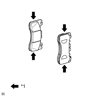
Text in Illustration *1 Disc brake grease Apply a light coat of disc brake grease to the front disc brake pads as shown in the illustration.
Note
-
When applying the disc brake grease, use the grease enclosed with a front disc brake pad kit or supplied grease (Part No. 90998-94072) or equivalent.
-
There should be no oil or grease on the friction surfaces of the pads and the disc.
-
-
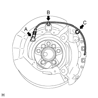
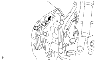
Connect the pad wear indicator wire connector (labeled A).
-
Attach the clamp (labeled B) and bleeder plug cap (labeled C).
-
Install the pad wear indicator wire and retainer to the inner pad.
-
Install the front disc brake pads to the front disc brake cylinder assembly.
-
Install the pad guide tie rod (lower) with the bolt.
- Torque:
- 30 N*m { 306 kgf*cm, 22 ft.*lbf }
-
Install the pad guide tie rod (upper) with the bolt.
- Torque:
- 30 N*m { 306 kgf*cm, 22 ft.*lbf }
-
Install the anti-rattle spring to the front disc brake cylinder assembly.
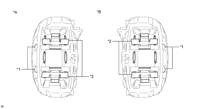
Text in Illustration *A for LH Side *B for RH Side *1 Pad Guide Tie Rod *2 Anti-rattle Spring Note
Securely install the anti-rattle spring in the correct position and facing the correct direction.
-
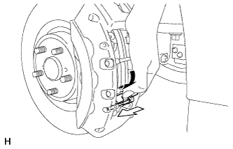
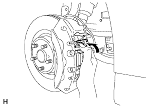
While holding the anti-rattle spring, insert the pad guide pin (lower) into the front disc brake cylinder assembly as shown in the illustration.
-
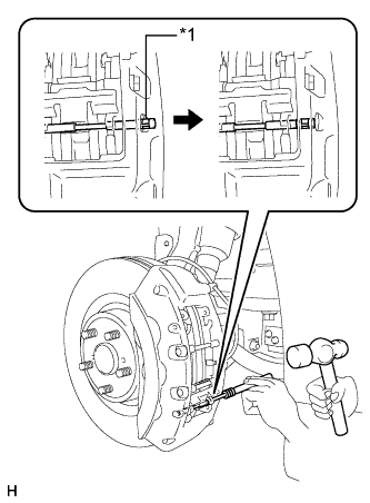
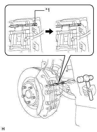
Text in Illustration *1 Ring Using a pin punch (5 mm) and hammer, install the pad guide pin (lower) to the front disc brake cylinder assembly.
Note
-
Do not damage the disc brake cylinder surface.
-
Securely attach the ring of the pad guide pin to the front disc brake cylinder assembly.
-
Make sure that the front disc brake anti-rattle spring is securely attached to the grooves of the front disc brake pad guide pin.
-
-
While holding the anti-rattle spring, insert the pad guide pin (upper) into the front disc brake cylinder assembly as shown in the illustration.
-
Text in Illustration *1 Ring Using a pin punch (5 mm) and hammer, install the pad guide pin (upper) to the front disc brake cylinder assembly.
Note
-
Do not damage the disc brake cylinder surface.
-
Securely attach the ring of the pad guide pin to the front disc brake cylinder assembly.
-
Make sure that the front disc brake anti-rattle spring is securely attached to the grooves of the front disc brake pad guide pin.
-
-
-
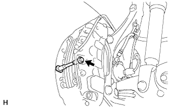
CONNECT FRONT FLEXIBLE HOSE
-
Connect the front flexible hose and a new gasket to the front disc brake cylinder assembly with a new union bolt.
- Torque:
- 39 N*m { 400 kgf*cm, 29 ft.*lbf }
Note
Install the flexible hose lock so that it fits securely in the lock hole in the disc brake cylinder assembly.
-
-
CONNECT CABLE TO AUXILIARY BATTERY NEGATIVE TERMINAL
Note
When disconnecting the cable, some systems need to be initialized after the cable is reconnected Click here.
-
INSTALL BATTERY SERVICE HOLE COVER LH
-

Text in Illustration *A for Standard *B for Ottoman Attach the battery service hole cover LH with the clip and fastening tape.
-
-
INSTALL DECK TRIM SIDE BOARD LH (w/o Spare Tire)
-

Attach the 2 clips to install the deck trim side board LH.
-
-
INSTALL DECK BOARD ASSEMBLY (w/o Spare Tire)

-
INSTALL LUGGAGE COMPARTMENT MAT SUB-ASSEMBLY (w/ Spare Tire)

-
BLEED BRAKE LINE
-
Bleed brake line.
-
Remove the brake master cylinder reservoir filler cap assembly.
-
Add brake fluid into the reservoir between MAX and MIN level on the brake fluid reservoir.
Brake fluid SAE J1703 or FMVSS No. 116 DOT3 -
Connect the intelligent tester to the DLC3 and turn the power switch on (IG).
-
Turn the intelligent tester on and enter the following menus: Chassis / ABS/VSC/TRC / Utility / Air Bleeding.
-
Select the "Usual air bleeding / All Line" and bleed brake line according to the intelligent tester display.
-
After air bleeding, tighten each bleeder plug.
- Torque:
- for Front Brake (except 6-pot caliper)
- 11 N*m { 110 kgf*cm, 8 ft.*lbf }
- for Front Brake (6-pot caliper)
- 19 N*m { 194 kgf*cm, 14 ft.*lbf }
- for Rear Brake
- 11 N*m { 110 kgf*cm, 8 ft.*lbf }
-
-
Clear the DTCs Click here.
-
Turn the intelligent tester off and turn the power switch off.
-
Inspect for brake fluid leaks.
-
Adjust the brake fluid level in the reservoir Click here.
-
-
INSTALL FRONT WHEEL
- Torque:
- 140 N*m { 1050 kgf*cm, 76 ft.*lbf }
-
CLEAR DTC
-
CHECK FOR DTC
-
If any DTC is output, perform the troubleshooting for that DTC Click here.
-