FRONT BRAKE (for 6-Pot Caliper) REMOVAL

Tech Tips
-
Use the same procedure for the RH and LH sides.
-
The following procedure is for the LH side.
Note
While the battery is connected, even if the engine switch is off, the brake control system activates when the brake pedal is depressed or the door courtesy switch turns on. Therefore during servicing of the brake system components, do not operate the brake pedal and open/close the doors while the battery is connected.
-
REMOVE LUGGAGE COMPARTMENT MAT SUB-ASSEMBLY (w/ Spare Tire)

-
REMOVE DECK BOARD ASSEMBLY (w/o Spare Tire)

-
REMOVE DECK TRIM SIDE BOARD LH (w/o Spare Tire)
-

Detach the 2 clips and remove the deck trim side board LH.
-
-
REMOVE BATTERY SERVICE HOLE COVER LH
-

Text in Illustration *A for Standard *B for Ottoman *1 Fastening Tape Detach the clip, fastening tape and remove the battery service hole cover LH.
-
-
PRECAUTION
Note
After turning the power switch off, waiting time may be required before disconnecting the cable from the auxiliary battery terminal. Therefore, make sure to read the disconnecting the cable from the auxiliary battery terminal notice before proceeding with work Click here.
-
DISCONNECT CABLE FROM AUXILIARY BATTERY NEGATIVE TERMINAL
Note
When disconnecting the cable, some systems need to be initialized after the cable is reconnected Click here.
-
REMOVE FRONT WHEEL
-
DRAIN BRAKE FLUID
Note
Wash brake fluid off immediately if it is spilled on any painted surface.
-
DISCONNECT FRONT FLEXIBLE HOSE
-
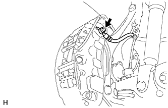
Remove the union bolt and gasket and disconnect the front flexible hose from the front disc brake cylinder assembly.
-
-
REMOVE FRONT DISC BRAKE PAD
Note
Be sure to inspect the front disc when replacing the brake pads with new ones Click here.
-
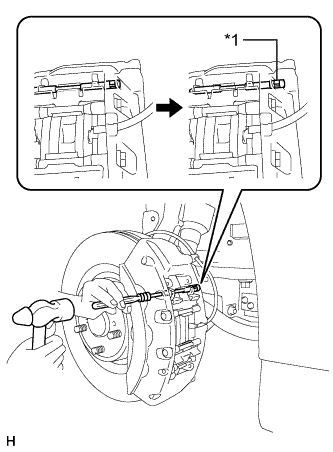
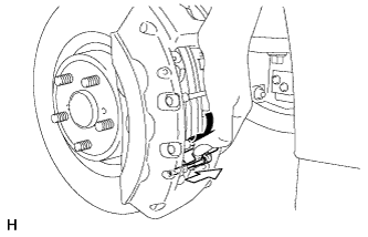
Text in Illustration *1 Ring Using a pin punch (5 mm) and hammer, detach the ring of the pad guide pin (upper) and push out the pad guide pin (upper) from the front disc brake cylinder assembly.
Note
Do not damage the disc brake cylinder surface.
-
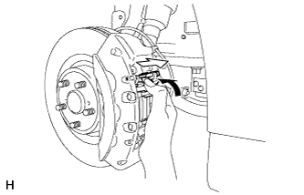
While holding the anti-rattle spring, remove the pad guide pin (upper) from the front disc brake cylinder assembly.
-
Remove the anti-rattle spring (upper) from the front disc brake cylinder assembly.
-
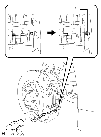
Text in Illustration *1 Ring Using a pin punch (5 mm) and hammer, detach the ring of pad guide pin (lower) and remove the pad guide pin (lower) from the front disc brake cylinder assembly.
Note
Do not damage the disc brake cylinder surface.
-
While holding the anti-rattle spring, remove the pad guide pin (lower) from the front disc brake cylinder assembly.
-
Remove the anti-rattle spring (lower) from the front disc brake cylinder assembly.
-
Remove the bolt and pad guide tie rod (upper) from the front disc brake cylinder assembly.
-
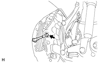
Remove the bolt and pad guide tie rod (lower) from the front disc brake cylinder assembly.
-
Remove the 2 front disc brake pads from the front disc brake cylinder assembly.
-
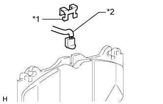
Text in Illustration *1 Retainer *2 Pad Wear Indicator Wire Remove the retainer and pad wear indicator wire from the inner pad.
-
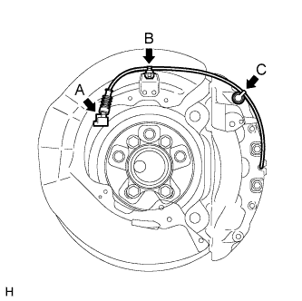
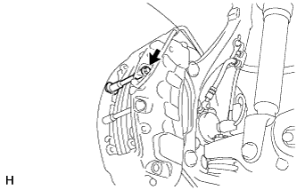
Disconnect the pad wear indicator wire connector (labeled A).
-
Detach the clamp (labeled B) and bleeder plug cap (labeled C).
-
-
REMOVE FRONT DISC BRAKE CYLINDER ASSEMBLY
-
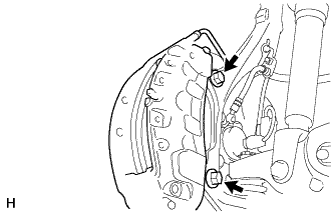
Remove the 2 bolts and front disc brake cylinder assembly from the knuckle.
-
-
REMOVE FRONT DISC
-
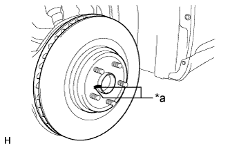
Text in Illustration *a Matchmark Remove the front disc from the front axle hub.
Tech Tips
Put matchmarks on the disc and axle hub.
-