BRAKE MASTER CYLINDER (for RHD) INSTALLATION

Note
While the battery is connected, even if the power switch is off, the brake control system activates when the brake pedal is depressed or the door courtesy switch turns on. Therefore during servicing of the brake system components, do not operate the brake pedal or open/close the doors while the battery is connected.
-
INSTALL BRAKE BOOSTER GASKET
-
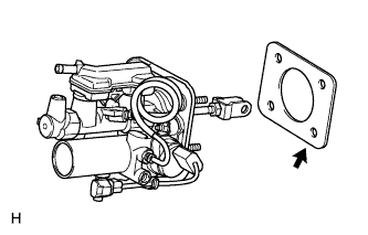
Install a new brake booster gasket to the brake master cylinder with simulator.
-
-
INSTALL BRAKE MASTER CYLINDER WITH SIMULATOR ASSEMBLY
-
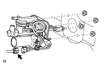
Install the brake master cylinder with simulator with the 4 nuts.
- Torque:
- 13 N*m { 130 kgf*cm, 9 ft.*lbf }
-
Connect the brake stroke simulator connector.
-
-
INSTALL PUSH ROD PIN
-
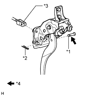
Text in Illustration *1 Push Rod Pin *2 Clip *3 Push Rod Clevis *4 Lithium soap base glycol grease Apply a light coat of lithium soap base glycol grease to the push rod pin.
-
Set the master cylinder push rod clevis in place, insert the push rod pin from outside of the vehicle and then install a new clip.
-
-
INSTALL BRAKE PEDAL RETURN SPRING
-
Install the spring between the pedal and steering column as shown in the illustration.
-
-
INSTALL RESERVOIR BRACKET
-
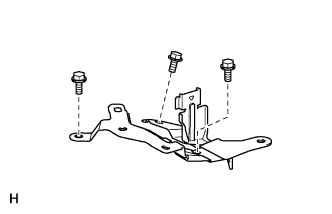
Install the reservoir bracket with the 3 bolts.
- Torque:
- 8.5 N*m { 87 kgf*cm, 75 in.*lbf }
-
-
INSTALL NO. 1 RESERVOIR HOSE
-
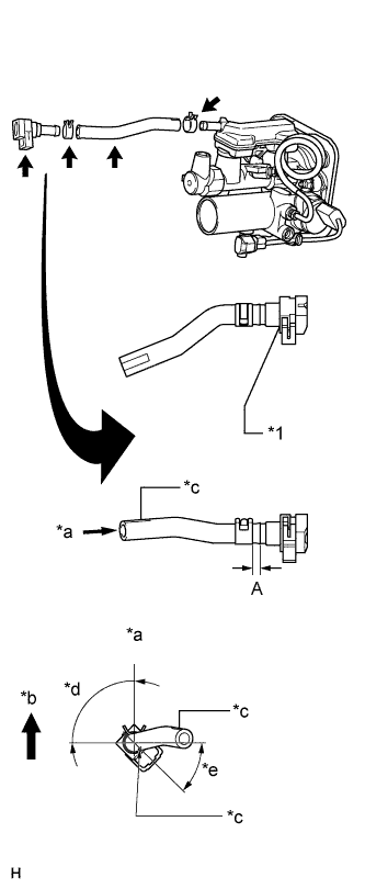
Text in Illustration *1 Reservoir Connector *a View B *b Upper *c Paint Mark *d 75°to 105° *e 30°to 60° Install the reservoir connector to the No. 1 reservoir hose with the hose clip as shown in the illustration.
Length "A" 4.0 to 7.0 mm (0.157 to 0.276 in.) -
With the paint mark on the hose's tip facing the top of the vehicle, install the No. 1 reservoir hose to the master cylinder with the hose clip.
Tech Tips
Install the hose clip so that its claws face the top of the vehicle.
-
-
INSTALL BRAKE MASTER CYLINDER RESERVOIR ASSEMBLY
-
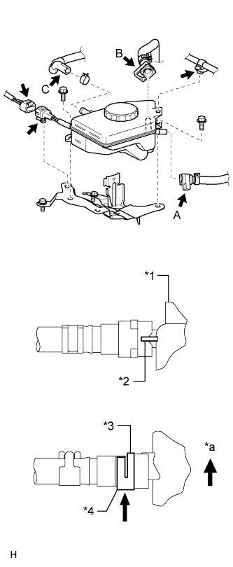
Text in Illustration *1 Reservoir *2 Rib *3 Claw *4 Lock *a Upper Connect the No. 1 reservoir hose (labeled A) and No. 2 brake actuator hose (labeled B) to the reservoir. The reservoir connector connecting procedure must be followed as described below:
-
Remove the foreign matter entry prevention plastic bags.
Note
Check that there is no damage or foreign objects on the connected part of the reservoir and reservoir connectors.
-
Insert the reservoir connector to the reservoir until the reservoir connector makes a "click" sound, so that the reservoir connector tip's groove is aligned with the reservoir's rib.
-
Securely set the lock of the reservoir connector.
-
Check that the reservoir connector lock's claw is securely attached.
-
-
With the paint mark on the hose's tip facing the top of the vehicle, connect the No. 1 brake actuator hose (labeled C) to the reservoir with the hose clip.
Tech Tips
Install the hose clip so that its claws face the top of the vehicle.
-
Connect the brake fluid level warning switch connector, and then attach the connector clamp to the reservoir bracket.
-
Install the brake fluid reservoir with the 2 bolts.
- Torque:
- 8.5 N*m { 87 kgf*cm, 75 in.*lbf }
-
Connect the wire harness clamp to the reservoir.
-
-
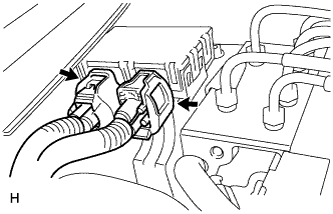
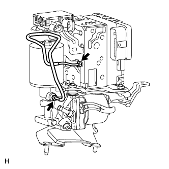
INSTALL BRAKE ACTUATOR AND BRAKE ACCUMULATOR PUMP ASSEMBLY
-
CONNECT NO. 3 RELAY BLOCK
-
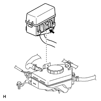
Install the No. 3 relay block to the reservoir bracket.
Note
Make sure that the claw of the No. 3 relay block is securely attached to the reservoir bracket.
-
-
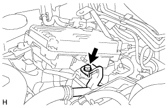
INSTALL SKID CONTROL ECU BRACKET
-
INSTALL SKID CONTROL ECU
-
CONNECT NO. 2 INVERTER COOLING PIPE
-
Connect the No. 2 inverter cooling pipe with the bolt.
- Torque:
- 13 N*m { 133 kgf*cm, 10 ft.*lbf }
-
-
CONNECT CABLE TO AUXILIARY BATTERY NEGATIVE TERMINAL
Note
-
Make sure that the 2 accumulator pump connectors are disconnected.
-
When disconnecting the cable, some systems need to be initialized after the cable is reconnected Click here.
-
-
INSTALL BATTERY SERVICE HOLE COVER LH
-

Text in Illustration *A for Standard *B for Ottoman Attach the battery service hole cover LH with the clip and fastening tape.
-
-
INSTALL DECK TRIM SIDE BOARD LH (w/o Spare Tire)
-

Attach the 2 clips to install the deck trim side board LH.
-
-
INSTALL DECK BOARD ASSEMBLY (w/o Spare Tire)

-
INSTALL LUGGAGE COMPARTMENT MAT SUB-ASSEMBLY (w/ Spare Tire)

-
CONNECT BRAKE ACCUMULATOR PUMP CONNECTOR
-
Add brake fluid into the reservoir between MAX and MIN line on the brake fluid reservoir.
Brake fluid SAE J1703 or FMVSS No. 116 DOT3 -
With the power switch off, connect the 2 brake accumulator pump connectors.
-
Turn the power switch on (IG) and check that the brake accumulator pump motor operates and stops.
-
Turn the power switch off.
-
-
BLEED BRAKE MASTER CYLINDER
-
Bleed brake master cylinder.
-
Remove the brake master cylinder reservoir filler cap assembly.
-
Add brake fluid into the reservoir between MAX and MIN level on the brake fluid reservoir.
Brake fluid SAE J1703 or FMVSS No. 116 DOT3 -
Connect the intelligent tester to the DLC3 and turn the power switch on (IG).
-
Turn the intelligent tester on and enter the following menus: Chassis / ABS/VSC/TRC / Utility / Air Bleeding.
-
Select the "Master Cylinder or Stroke Simulator has been removed" and bleed brake master cylinder according to the intelligent tester display.
-
After air bleeding, tighten each bleeder plug.
- Torque:
- for Front Brake (except 6-pot caliper)
- 11 N*m { 110 kgf*cm, 8 ft.*lbf }
- for Front Brake (6-pot caliper)
- 19 N*m { 194 kgf*cm, 14 ft.*lbf }
- for Rear Brake
- 11 N*m { 110 kgf*cm, 8 ft.*lbf }
-
-
Clear the DTCs Click here.
-
Turn the intelligent tester off and turn the power switch off.
-
Inspect for brake fluid leaks.
-
Adjust the brake fluid level in the reservoir Click here.
-
-
CHECK AND ADJUST BRAKE PEDAL
-
INSTALL NO. 1 INSTRUMENT PANEL SAFETY PAD SUB-ASSEMBLY
-
INSTALL FRONT WHEEL
- Torque:
- 140 N*m { 1428 kgf*cm, 103 ft.*lbf }
-
INSTALL COWL TOP VENTILATOR LOUVER SUB-ASSEMBLY
-
INSTALL V-BANK COVER SUB-ASSEMBLY
-

After sliding the V-bank cover sub-assembly from the vehicle front to the rear to attach the 2 clips labeled A, attach the 4 clips labeled B and install the V-bank cover sub-assembly.
CAUTION:
-
Make sure the clips are attached securely.
-
Attaching the clips forcefully or hitting the top of the clips may damage them.
-
-
-
PERFORM LINEAR VALVE OFFSET LEARNING
-
When the brake master cylinder with simulator assembly is replaced, perform the linear valve offset learning Click here.
-
-
CHECK BRAKE ACTUATOR WITH TESTER
-
Check the brake actuator and pressure sensor Click here.
-
-
CHECK BRAKE MASTER CYLINDER WITH TESTER
-
Check the brake master cylinder and stroke simulator Click here.
-
-
CHECK SRS WARNING LIGHT
-
RESET CUSTOMIZE PROGRAM
Note
Reset the AUTO TILT AWAY function setting to the previous condition by changing the customize parameter Click here.
-
CLEAR THE DTC
-
CHECK MASTER CYLINDER PRESSURE SENSOR SIGNAL
-
CHECK FOR DTC
-
Check for DTC. If any DTC is output, perform the troubleshooting for that DTC Click here.
-
-
READ VALUE OF ACCUMULATOR PRESSURE SENSOR OUTPUT VOLTAGE
Tech Tips
If removing and installing the No. 3 brake actuator tube, check for a brake fluid leak from the No. 3 tube connection area by monitoring the accumulator pressure sensor output value from the brake actuator. Directly checking for a brake fluid leak from the No. 3 tube connection area is difficult.
-
Turn the power switch OFF.
-
Connect the intelligent tester to the DLC3.
-
Turn the power switch ON (IG).
-
Operate the intelligent tester according to the display and select "DATA LIST".
Skid control ECU: Tester Display Measurement Item/Range Normal Condition Diagnostic Note Accumulator Pressure Sensor Accumulator pressure sensor / min.: 0 V, max.: 5 V Specified value: 2.6 to 3.8 V - -
Depress the brake pedal 4 or 5 times to operate the pump motor, and check the output value on the intelligent tester with the motor stopped (not braking).
OK Accumulator pressure sensor's output voltage drops 0.2 V or less for 30 seconds. If the voltage drops more than 0.2 V, there may be a brake fluid leak from the No. 3 brake actuator tube connection area. Remove the brake actuator and brake accumulator pump, and then repeat the procedures above from the retightening of the 2 union nuts of the No. 3 brake actuator tube.
- Torque:
- Specified tightening torque
- 15 N*m { 155 kgf*cm, 11 ft.*lbf }
Tech Tips
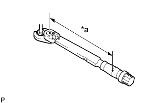
Text in Illustration *a Torque Wrench Fulcrum Length
-
Calculate the torque wrench reading when changing the fulcrum length of the torque wrench Click here.
-
When using a union nut wrench (fulcrum length of 22 mm (0.8661 in.)) + torque wrench (fulcrum length of 162 mm (6.3779 in.)): 13 N*m (137 kgf*cm, 10 ft.*lbf)
-