BRAKE MASTER CYLINDER (for LHD) REMOVAL

Note
While the battery is connected, even if the power switch is off, the brake control system activates when the brake pedal is depressed or the door courtesy switch turns on. Therefore during servicing of the brake system components, do not operate the brake pedal or open/close the doors while the battery is connected.
-
PRECAUTION
CAUTION:
Be sure to read the Precaution thoroughly before servicing Click here.
Note
After turning the power switch off, waiting time may be required before disconnecting the cable from the auxiliary battery terminal, Therefore, make sure to read the disconnecting the cable from the auxiliary battery terminal notice before proceeding with work Click here.
-
REMOVE V-BANK COVER SUB-ASSEMBLY
-

While using both hands, lift the rear side of the V-bank cover sub-assembly upwards to detach the 4 clips labeled B. Slide the V-bank cover sub-assembly towards the front of the vehicle to detach the 2 clips labeled A, and remove the V-bank cover sub-assembly.
Note
The V-bank cover sub-assembly may be damaged if its front and rear are lifted at the same time.
-
-
REMOVE COWL TOP VENTILATOR LOUVER SUB-ASSEMBLY
-
DISCONNECT BRAKE ACCUMULATOR PUMP CONNECTOR
-
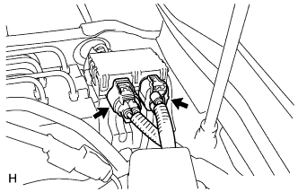
With the power switch off, disconnect the 2 brake accumulator pump connectors.
-
-
PERFORM ACCUMULATOR ZERO DOWN
-
Drain the brake fluid in the reservoir tank near the MIN line.
-
Connect the intelligent tester to the DLC3 with the power switch off.
-
Turn the power switch on (IG).
-
Turn the intelligent tester on and enter the following menus: Chassis / ABS/VSC/TRC / Utility / ECB (Electronically Controlled Brake system) Utility / Zero Down.
Tech Tips
Using the intelligent tester to perform accumulator zero down causes the pressurized fluid in the accumulator to be returned to the brake fluid reservoir.
-
When the buzzer sounds, turn the power switch off.
-
Turn the intelligent tester off.
-
-
REMOVE LUGGAGE COMPARTMENT MAT SUB-ASSEMBLY (w/ Spare Tire)

-
REMOVE DECK BOARD ASSEMBLY (w/o Spare Tire)

-
REMOVE DECK TRIM SIDE BOARD LH (w/o Spare Tire)
-

Detach the 2 clips and remove the deck trim side board LH.
-
-
REMOVE BATTERY SERVICE HOLE COVER LH
-

Text in Illustration *A for Standard *B for Ottoman *1 Fastening Tape Detach the clip, fastening tape and remove the battery service hole cover LH.
-
-
DISCONNECT CABLE FROM AUXILIARY BATTERY NEGATIVE TERMINAL
-
Disable the AUTO TILT AWAY function by changing the customize parameter Click here.
Note
Record the current customize parameter setting (whether the AUTO TILT AWAY function is enabled or disabled) in order to restore the current setting after finishing the operation.
Tech Tips
Performing the above operation causes the AUTO TILT AWAY function to be disabled when the power switch is turned off.
-
Turn the power switch ON (IG). Operate the tilt and telescopic switch to fully extend and lower the steering column.
-
Turn the power switch off and disconnect the cable from the negative (-) battery terminal.
Note
When disconnecting the cable, some systems need to be initialized after the cable is reconnected Click here.
-
-
DISCONNECT NO. 1 MOTOR COOLING PIPE
-
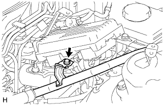
Remove the bolt.
-
Disconnect the No. 1 motor cooling pipe from the skid control ECU bracket.
-
-
REMOVE SKID CONTROL ECU
-
REMOVE SKID CONTROL ECU BRACKET
-
REMOVE BRAKE ACTUATOR AND BRAKE ACCUMULATOR PUMP ASSEMBLY
-
DISCONNECT NO. 3 RELAY BLOCK
-
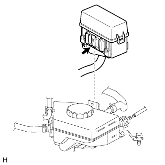
While pushing the claw of the No. 3 relay block, pull out the No. 3 relay block and disconnect it from the reservoir bracket.
Note
Do not allow brake fluid to contact the No. 3 relay block.
-
-
REMOVE BRAKE MASTER CYLINDER RESERVOIR ASSEMBLY
-
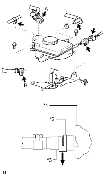
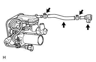
Text in Illustration *1 Reservoir *2 Lock *3 Reservoir Connector Disconnect the wire harness clamp from the reservoir.
-
Detach the connector clamp from the reservoir bracket, and then disconnect the brake fluid level warning switch connector.
-
Disconnect the No. 1 brake actuator hose from the reservoir.
-
Release the locks of the reservoir connectors. Then disconnect the No. 2 brake actuator hose (labeled A) and No. 1 reservoir hose (labeled B) from the reservoir.
Note
-
Check for any dirt and foreign matter contamination in the reservoir and around the reservoir connector. Clean if necessary. Foreign matter may damage the O-rings or cause leaks in the seal between the reservoir and reservoir connector.
-
Do not use any tools to separate the reservoir and reservoir connector.
-
If the reservoir and reservoir connector are stuck together, pinch the tube between your fingers and turn it carefully to free it. Then disconnect the hose.
-
Put the reservoir and reservoir connector ends in plastic bags to prevent damage and dirt contamination.
-
-
Remove the 2 bolts and brake fluid reservoir.
-
-
REMOVE NO. 1 RESERVOIR HOSE
-
Remove the hose clip and No. 1 reservoir hose from the master cylinder.
-
Remove the hose clip and reservoir connector from the No. 1 reservoir hose.
-
-
REMOVE RESERVOIR BRACKET
-
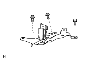
Remove the 3 bolts and reservoir bracket.
-
-
REMOVE FRONT WHEEL
-
REMOVE NO. 1 INSTRUMENT PANEL SAFETY PAD SUB-ASSEMBLY
-
REMOVE BRAKE PEDAL RETURN SPRING
-
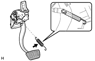
Remove the spring.
-
-
REMOVE PUSH ROD PIN
-
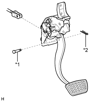
Text in Illustration *1 Push Rod Pin *2 Clip Remove the clip and push rod pin.
-
-
REMOVE BRAKE MASTER CYLINDER WITH SIMULATOR ASSEMBLY
-
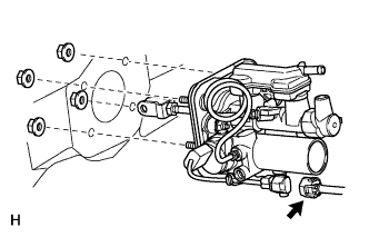
Disconnect the brake stroke simulator connector.
-
Remove the 4 nuts and brake master cylinder with simulator.
-
-
REMOVE BRAKE BOOSTER GASKET
-
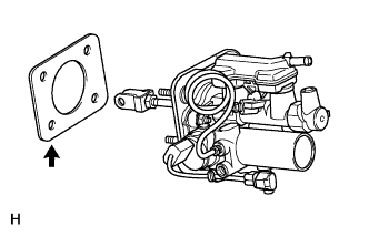
Remove the brake booster gasket from the brake master cylinder with simulator.
-