ABS MOTOR RELAY ON-VEHICLE INSPECTION

Note
While the battery is connected, even if the power switch is OFF, the brake control system activates when the brake pedal is depressed or the door courtesy switch turns on. Therefore during servicing of the brake system components, do not operate the brake pedal or open/close the doors while the battery is connected.
-
CHECK ABS MOTOR RELAY (ABS MTR1)
Tech Tips
The ABS motor relay (ABS MTR1) cannot be removed and inspected, as it is an internal relay of the engine room junction block.
-
Turn the power switch OFF.
-
Connect the intelligent tester to the DLC3.
-
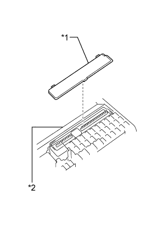
Text in Illustration *1 Terminal Cover *2 Engine Room No. 2 Junction Block Remove the relay inspection terminal cover of the engine room No. 2 junction block.
-
Turn the power switch ON (IG).
-
Using the intelligent tester, perform the Active Test for the ABS motor relay (ABS MTR1) and measure the voltage between the relay inspection terminals of the engine room junction block.
Tech Tips
As the ABS motor relay (ABS MTR1) is a semiconductor relay, there are no operation sounds.
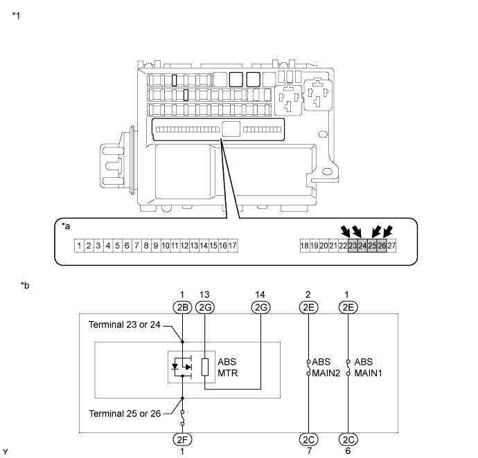
Standard voltage Tester Connection Switch Condition Specified Condition Terminal 23 or 24 - Body ground Motor relay: ON 11 to 14 V Motor relay: OFF 0 V Terminal 25 or 26 - Body ground - 11 to 14 V Text in Illustration *1 Engine Room No. 2 Junction Block - - *a Terminal for Relay Inspection *b Inner Circuit If the result is not as specified, check the harness and connector and replace them as necessary.
If the harness and connector are in good condition, replace the engine room junction block assembly.
-
-
CHECK ABS MOTOR RELAY (ABS MTR2)
-
Remove the ABS motor relay from the No. 3 relay block.
-
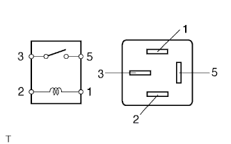
Measure the resistance according to the value(s) in the table below.
Standard resistance Tester Connection Condition Specified Condition 3 - 5 When battery voltage is not applied to terminals 1 and 2 10 kΩ or higher 3 - 5 When battery voltage is applied to terminals 1 and 2 Below 1 Ω If the result is not as specified, replace the relay.
-
Install the ABS motor relay.
-