BRAKE CONTROL POWER SUPPLY INSTALLATION

Note
While the battery is connected, even if the power switch is OFF, the brake control system activates when the brake pedal is depressed or the door courtesy switch turns on. Therefore during servicing of the brake system components, do not operate the brake pedal or open/close the doors while the battery is connected.
-
INSTALL NO. 1 BRAKE CONTROL POWER SUPPLY BRACKET
-
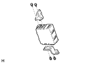
Install the 2 brackets with the 4 bolts.
- Torque:
- 8.5 N*m { 87 kgf*cm, 75 in.*lbf }
Note
Do not drop the brake control power supply. If the brake control power supply has been dropped, replace the brake control power supply with a new one.
-
-
INSTALL BRAKE CONTROL POWER SUPPLY ASSEMBLY
-
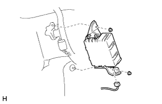
Connect the connector to the brake control power supply.
-
Install the brake control power supply with the 2 nuts.
- Torque:
- 8.0 N*m { 82 kgf*cm, 71 in.*lbf }
-
-
INSTALL LUGGAGE COMPARTMENT TRIM COVER ASSEMBLY RH
-
CONNECT CABLE TO AUXILIARY BATTERY NEGATIVE TERMINAL
Note
When disconnecting the cable, some systems need to be initialized after the cable is reconnected Click here.
-
INSTALL BATTERY SERVICE HOLE COVER LH
-

Text in Illustration *A for Standard *B for Ottoman Attach the battery service hole cover LH with the clip and fastening tape.
-
-
INSTALL DECK TRIM SIDE BOARD LH (w/o Spare Tire)
-

Attach the 2 clips to install the deck trim side board LH.
-
-
INSTALL DECK BOARD ASSEMBLY (w/o Spare Tire)

-
INSTALL LUGGAGE COMPARTMENT MAT SUB-ASSEMBLY (w/ Spare Tire)

-
CHECK AND CLEAR DTC