SKID CONTROL ECU (for RHD) REMOVAL

Note
While the battery is connected, even if the power switch is OFF, the brake control system activates when the brake pedal is depressed or the door courtesy switch turns on. Therefore during servicing of the brake system components, do not operate the brake pedal or open/close the doors while the battery is connected.
-
REMOVE V-BANK COVER SUB-ASSEMBLY
-

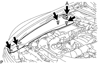
While using both hands, lift the rear side of the V-bank cover sub-assembly upwards to detach the 4 clips labeled B. Slide the V-bank cover sub-assembly towards the front of the vehicle to detach the 2 clips labeled A, and remove the V-bank cover sub-assembly.
Note
The V-bank cover sub-assembly may be damaged if its front and rear are lifted at the same time.
-
-
REMOVE ENGINE ROOM SIDE COVER RH
-
for LHD:
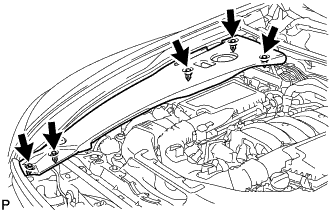
Remove the 5 clips and engine room side cover RH.
Note
Remove the clip labeled A by turning it to prevent the engine room side cover RH and bracket from being damaged.
Tech Tips
The clip labeled A cannot be removed from the engine room side cover RH.
-
for RHD:
Remove the 5 clips and engine room side cover RH.
-
-
REMOVE LUGGAGE COMPARTMENT MAT SUB-ASSEMBLY (w/ Spare Tire)

-
REMOVE DECK BOARD ASSEMBLY (w/o Spare Tire)

-
REMOVE DECK TRIM SIDE BOARD LH (w/o Spare Tire)
-

Detach the 2 clips and remove the deck trim side board LH.
-
-
REMOVE BATTERY SERVICE HOLE COVER LH
-

Text in Illustration *A for Standard *B for Ottoman *1 Fastening Tape Detach the clip, fastening tape and remove the battery service hole cover LH.
-
-
PRECAUTION
Note
After turning the power switch off, waiting time may be required before disconnecting the cable from the auxiliary battery terminal. Therefore, make sure to read the disconnecting the cable from the auxiliary battery terminal notice before proceeding with work Click here.
-
DISCONNECT CABLE FROM AUXILIARY BATTERY NEGATIVE TERMINAL
Note
When disconnecting the cable, some systems need to be initialized after the cable is reconnected Click here.
-
DISCONNECT NO. 2 INVERTER COOLING PIPE
-
Remove the bolt.
-
Disconnect the No. 2 inverter cooling pipe from the skid control ECU bracket.
-
-
REMOVE SKID CONTROL ECU
-
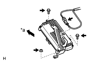
Text in Illustration *a Front Disconnect the short connector for the brake stroke simulator from the bracket of the skid control ECU.
-
Remove the 2 bolts, nut and ECU.
-
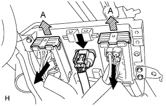
Pull the 2 lock levers upward to release the locks and disconnect the 2 connectors (labeled A).
-
Disconnect the connector.
-
-
DISCONNECT NO. 3 RELAY BLOCK
-
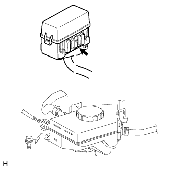
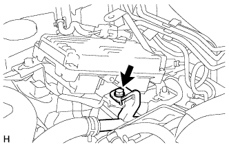
While pushing the claw of the No. 3 relay block, pull out the No. 3 relay block and disconnect it from the reservoir bracket.
Note
Do not allow brake fluid to contact the No. 3 relay block.
-
-
DISCONNECT BRAKE FLUID RESERVOIR
-
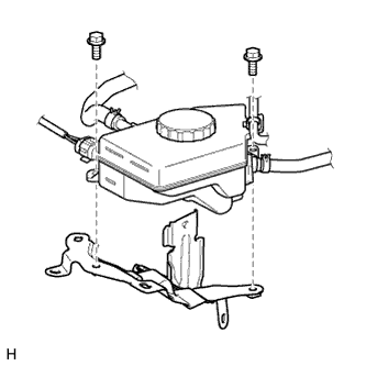
Remove the 2 bolts.
-
Disconnect the brake fluid reservoir.
-
-
REMOVE SKID CONTROL ECU BRACKET
-
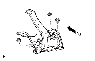
Text in Illustration *a Front Remove the 2 nuts, bolt and bracket.
-