SKID CONTROL ECU (for LHD) INSTALLATION

Note
While the battery is connected, even if the power switch is OFF, the brake control system activates when the brake pedal is depressed or the door courtesy switch turns on. Therefore during servicing of the brake system components, do not operate the brake pedal or open/close the doors while the battery is connected.
-
INSTALL SKID CONTROL ECU BRACKET
-
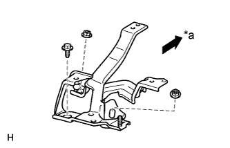
Text in Illustration *a Front Install the bracket with the bolt and 2 nuts.
- Torque:
- 8.5 N*m { 87 kgf*cm, 75 in.*lbf }
-
-
CONNECT BRAKE FLUID RESERVOIR
-
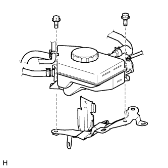
Install the brake fluid reservoir with the 2 bolts.
- Torque:
- 8.5 N*m { 87 kgf*cm, 75 in.*lbf }
-
-
CONNECT NO. 3 RELAY BLOCK
-
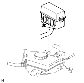
Install the No. 3 relay block to the reservoir bracket.
Note
Make sure that the claw of the No. 3 relay block is securely attached to the reservoir bracket.
-
-
INSTALL SKID CONTROL ECU
-
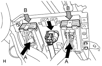
Connect the 2 connectors (labeled A) and press the lock levers down to lock the connectors (labeled B).
Note
Make sure that the lock levers securely lock the connectors.
-
Connect the connector.
-
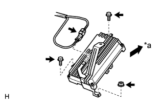
Text in Illustration *a Front Install the ECU with the 2 bolts and nut.
- Torque:
- 8.5 N*m { 87 kgf*cm, 75 in.*lbf }
-
Connect the short connector for the brake stroke simulator to the bracket of the skid control ECU.
-
-
CONNECT NO. 1 MOTOR COOLING PIPE
-
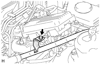
Connect the No. 1 motor cooling pipe with the bolt.
- Torque:
- 13 N*m { 133 kgf*cm, 10 ft.*lbf }
-
-
CONNECT CABLE TO AUXILIARY BATTERY NEGATIVE TERMINAL
Note
When disconnecting the cable, some systems need to be initialized after the cable is reconnected Click here.
-
INSTALL BATTERY SERVICE HOLE COVER LH
-

Text in Illustration *A for Standard *B for Ottoman Attach the battery service hole cover LH with the clip and fastening tape.
-
-
INSTALL DECK TRIM SIDE BOARD LH (w/o Spare Tire)
-

Attach the 2 clips to install the deck trim side board LH.
-
-
INSTALL DECK BOARD ASSEMBLY (w/o Spare Tire)

-
INSTALL LUGGAGE COMPARTMENT MAT SUB-ASSEMBLY (w/ Spare Tire)

-
CHECK AND CLEAR DTC
-
PERFORM LINEAR VALVE OFFSET LEARNING
-
PERFORM YAW RATE SENSOR ZERO POINT CALIBRATION
-
PERFORM TEST MODE INSPECTION
-
INSTALL ENGINE ROOM SIDE COVER LH
-
Install the engine room side cover LH with the 5 clips.
-
-
INSTALL V-BANK COVER SUB-ASSEMBLY
-

After sliding the V-bank cover sub-assembly from the vehicle front to the rear to attach the 2 clips labeled A, attach the 4 clips labeled B and install the V-bank cover sub-assembly.
CAUTION:
-
Make sure the clips are attached securely.
-
Attaching the clips forcefully or hitting the top of the clips may damage them.
-
-