While the battery is connected, even if the power switch is off, the brake control system activates when the brake pedal is depressed or the door courtesy switch turns on. Therefore during servicing of the brake system components, do not operate the brake pedal or open/close the doors while the battery is connected.
- Click here
INSTALL BRAKE PEDAL SUPPORT ASSEMBLY
-
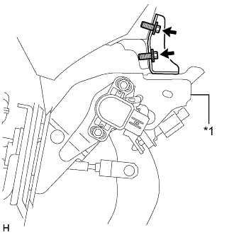
Install the brake pedal support with the 2 bolts.
19 N*m 195 kgf*cm 14 ft.*lbf Table 1. Text in Illustration *1 Brake Pedal Support -
Install the 4 nuts.
13 N*m 130 kgf*cm 9 ft.*lbf
-
- Click here
INSTALL PUSH ROD PIN
-
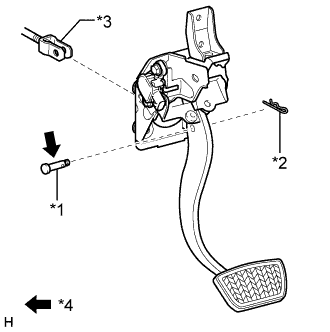
Apply a light coat of lithium soap base glycol grease to the push rod pin.
Table 2. Text in Illustration *1 Push Rod Pin *2 Clip *3 Push Rod Clevis *4 Lithium soap base glycol grease -
Set the master cylinder push rod clevis in place, insert the push rod pin from outside of the vehicle and then install a new clip.
-
- Click here
INSTALL BRAKE PEDAL RETURN SPRING
-
Install the spring between the pedal and steering column.
-
- Click here
CONNECT CONNECTORS
-
Connect the stop light switch connector and then attach the wire harness clamp.
-
Connect the brake pedal stroke sensor connector.
-
- Click here
CHECK BRAKE DRAG
- Click here
CHECK AND ADJUST BRAKE PEDAL
- Click here
INSTALL INSTRUMENT PANEL SAFETY PAD SUB-ASSEMBLY
- Click here
CONNECT CABLE TO AUXILIARY BATTERY NEGATIVE TERMINAL
Note:When disconnecting the cable, some systems need to be initialized after the cable is reconnected (Click here).
- Click here
INSTALL BATTERY SERVICE HOLE COVER LH
-

Attach the battery service hole cover LH with the clip and fastening tape.
Table 3. Text in Illustration *A for Standard *B for Ottoman
-
- Click here
INSTALL DECK TRIM SIDE BOARD LH (w/o Spare Tire)
-

Attach the 2 clips to install the deck trim side board LH.
-
-
Click here
INSTALL DECK BOARD ASSEMBLY (w/o Spare Tire)
-
Click here
INSTALL LUGGAGE COMPARTMENT MAT SUB-ASSEMBLY (w/ Spare Tire)
- Click here
CHECK SRS WARNING LIGHT