FRONT SPEED SENSOR INSTALLATION

Tech Tips
-
The procedures listed below are for the RH side.
-
Use the same procedures for the LH side and RH side.
Note
While the battery is connected, even if the power switch is OFF, the brake control system activates when the brake pedal is depressed or the door courtesy switch turns on. Therefore during servicing of the brake system components, do not operate the brake pedal or open/close the doors while the battery is connected.
-
INSTALL FRONT SPEED SENSOR RH
-
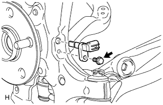
Install the sensor with the bolt.
- Torque:
- 8.5 N*m { 87 kgf*cm, 75 in.*lbf }
Note
-
The speed sensor is easily damaged.
When installing the speed sensor to the axle hub, do not use excessive force to rotate and install it.
-
Prevent foreign matter from attaching to the sensor tip.
-
Do not drop the sensor. If the sensor has been dropped, replace the sensor with a new one.
-
-
INSTALL SKID CONTROL SENSOR WIRE
-
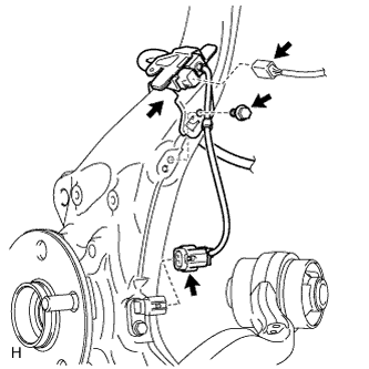
Connect the connector to the front speed sensor.
-
Install the sensor clamp with the bolt.
- Torque:
- 8.5 N*m { 87 kgf*cm, 75 in.*lbf }
-
Connect the pad wear indicator connector.
-
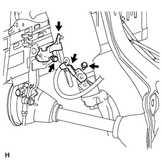
Install the 2 sensor clamps with the 2 bolts.
- Torque:
- 8.5 N*m { 87 kgf*cm, 75 in.*lbf }
Note
Do not twist the sensor wire when installing the clamps.
-
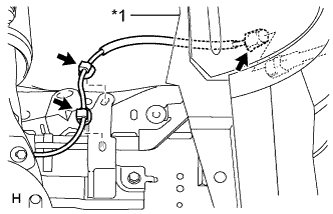
Text in Illustration *1 Fender Liner Attach the 2 sensor clips.
- Torque:
- 8.5 N*m { 87 kgf*cm, 75 in.*lbf }
Note
Do not twist the sensor wire when installing the clamp.
-
Connect the sensor connector.
-
Connect the front fender liner.
-
-
INSTALL FRONT WHEEL
- Torque:
- 140 N*m { 1428 kgf*cm, 103 ft.*lbf }
-
CONNECT CABLE TO AUXILIARY BATTERY NEGATIVE TERMINAL
Note
When disconnecting the cable, some systems need to be initialized after the cable is reconnected Click here.
-
INSTALL BATTERY SERVICE HOLE COVER LH
-

Text in Illustration *A for Standard *B for Ottoman Attach the battery service hole cover LH with the clip and fastening tape.
-
-
INSTALL DECK TRIM SIDE BOARD LH (w/o Spare Tire)
-

Attach the 2 clips to install the deck trim side board LH.
-
-
INSTALL DECK BOARD ASSEMBLY (w/o Spare Tire)

-
INSTALL LUGGAGE COMPARTMENT MAT SUB-ASSEMBLY (w/ Spare Tire)

-
CHECK SPEED SENSOR SIGNAL