BRAKE ACTUATOR (for RHD) REMOVAL

Note
While the battery is connected, even if the power switch is OFF, the brake control system activates when the brake pedal is depressed or the door courtesy switch turns on. Therefore during servicing of the brake system components, do not operate the brake pedal or open/close the doors while the battery is connected.
-
REMOVE V-BANK COVER SUB-ASSEMBLY
-

While using both hands, lift the rear side of the V-bank cover sub-assembly upwards to detach the 4 clips labeled B. Slide the V-bank cover sub-assembly towards the front of the vehicle to detach the 2 clips labeled A, and remove the V-bank cover sub-assembly.
Note
The V-bank cover sub-assembly may be damaged if its front and rear are lifted at the same time.
-
-
REMOVE COWL TOP VENTILATOR LOUVER SUB-ASSEMBLY
-
DISCONNECT BRAKE ACCUMULATOR PUMP CONNECTOR
-
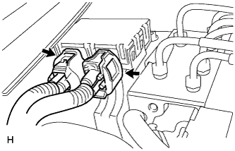
With the power switch off, disconnect the 2 brake accumulator pump connectors.
-
-
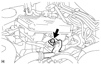
PERFORM ACCUMULATOR ZERO DOWN
-
Drain the brake fluid in the reservoir tank near the MIN line.
-
Connect the intelligent tester to the DLC3 with the power switch off.
-
Turn the power switch on (IG).
-
Turn the intelligent tester on and enter the following menus: Chassis / ABS/VSC/TRC / Utility / ECB (Electronically Controlled Brake system) Utility / Zero Down.
Tech Tips
Using the intelligent tester to perform accumulator zero down causes the pressurized fluid in the accumulator to be returned to the brake fluid reservoir.
-
When the buzzer sounds, turn the power switch off.
-
Turn the intelligent tester off.
-
-
REMOVE LUGGAGE COMPARTMENT MAT SUB-ASSEMBLY (w/ Spare Tire)

-
REMOVE DECK BOARD ASSEMBLY (w/o Spare Tire)

-
REMOVE DECK TRIM SIDE BOARD LH (w/o Spare Tire)
-

Detach the 2 clips and remove the deck trim side board LH.
-
-
REMOVE BATTERY SERVICE HOLE COVER LH
-

Text in Illustration *A for Standard *B for Ottoman *1 Fastening Tape Detach the clip, fastening tape and remove the battery service hole cover LH.
-
-
PRECAUTION
Note
After turning the power switch off, waiting time may be required before disconnecting the cable from the auxiliary battery terminal. Therefore, make sure to read the disconnecting the cable from the auxiliary batter terminal notice before proceeding with work Click here.
-
DISCONNECT CABLE FROM AUXILIARY BATTERY NEGATIVE TERMINAL
Note
When disconnecting the cable, some systems need to be initialized after the cable is reconnected Click here.
-
DISCONNECT NO. 2 INVERTER COOLING PIPE
-
Remove the bolt.
-
Disconnect the No. 2 inverter cooling pipe from the skid control ECU bracket.
-
-
REMOVE SKID CONTROL ECU
-
REMOVE SKID CONTROL ECU BRACKET
-
DISCONNECT NO. 3 RELAY BLOCK
-
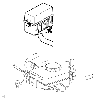
While pushing the claw of the No. 3 relay block, pull out the No. 3 relay block and disconnect it from the reservoir bracket.
Note
Do not allow brake fluid to contact the No. 3 relay block.
-
-
REMOVE BRAKE MASTER CYLINDER RESERVOIR ASSEMBLY
-
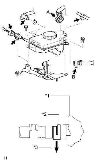
Text in Illustration *1 Reservoir *2 Lock *3 Reservoir Connector Disconnect the wire harness clamp from the reservoir.
-
Detach the connector clamp from the reservoir bracket, and then disconnect the brake fluid level warning switch connector.
-
Disconnect the No. 1 brake actuator hose from the reservoir.
-
Release the locks of the reservoir connectors. Then disconnect the No. 2 brake actuator hose (labeled A) and No. 1 reservoir hose (labeled B) from the reservoir.
Note
-
Check for any dirt and foreign matter contamination in the reservoir and around the reservoir connector. Clean if necessary. Foreign matter may damage the O-rings or cause leaks in the seal between the reservoir and reservoir connector.
-
Do not use any tools to separate the reservoir and reservoir connector.
-
If the reservoir and reservoir connector are stuck together, pinch the tube between your fingers and turn it carefully to free it. Then disconnect the hose.
-
Put the reservoir and reservoir connector ends in plastic bags to prevent damage and dirt contamination.
-
-
Remove the 2 bolts and brake fluid reservoir.
-
-
REMOVE NO. 1 RESERVOIR HOSE
-
Remove the hose clip and No. 1 reservoir hose from the master cylinder.
-
Remove the hose clip and reservoir connector from the No. 1 reservoir hose.
-
-
REMOVE RESERVOIR BRACKET
-
Remove the 3 bolts and reservoir bracket.
-
-
REMOVE FRONT WHEEL
-
DISCONNECT BRAKE TUBE
-
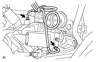
Release the lock lever and disconnect the brake actuator connector.
Note
Do not allow brake fluid to contact the connector face.
-
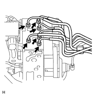
Using a union nut wrench, disconnect the 6 brake tubes from the actuator.
-
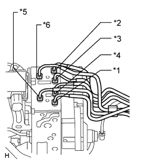
Use tags or make a note to identify the reconnection locations.
-
*1: To FR RH
-
*2: To FR LH
-
*3: To: RR RH
-
*4: To RR LH
-
*5: From Brake Master Cylinder
-
*6: From Brake Stroke Simulator Cylinder
-
-
Using a union nut wrench, disconnect the No. 1 and No. 2 brake actuator tubes.
Note
Do not damage the No. 1 and No. 2 brake actuator tubes.
-
-
REMOVE BRAKE ACTUATOR AND BRAKE ACCUMULATOR PUMP ASSEMBLY
-
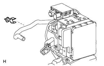
Disconnect the No. 1 brake actuator hose from the clamp and then remove the clamp.
-
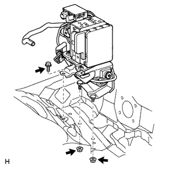
Disconnect the front fender liner rear side and then remove the 2 nuts.
-
Remove the bolt, and brake actuator and brake accumulator pump.
Note
-
Do not damage the brake tubes.
-
When removing the brake actuator and brake accumulator pump from the vehicle, do not hold the connector, harness, hose or tube parts.
-
Do not drop the brake actuator and brake accumulator pump. Do not use parts that have been dropped.
-
-
-
REMOVE NO. 5 BRAKE ACTUATOR BRACKET
-
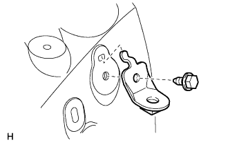
Remove the bolt and No. 5 brake actuator bracket.
-
-
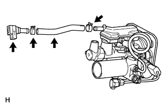
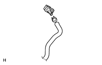
REMOVE NO. 1 BRAKE ACTUATOR HOSE
Note
When disconnecting the hose, be careful that there is no excessive weight applied to the union of the brake actuator (especially in the union rotation direction).
-
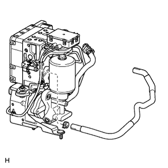
Remove the hose clip and No. 1 brake actuator hose.
-
-
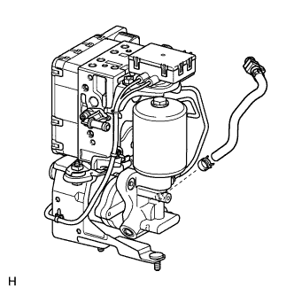
REMOVE BRAKE ACTUATOR PROTECTOR
-
Remove the protector.
-
-
REMOVE NO. 2 BRAKE ACTUATOR HOSE
Note
When disconnecting the hose, be careful that there is no excessive weight applied to the union of the brake accumulator pump (especially in the union rotation direction).
-
Remove the hose clip and No. 2 brake actuator hose.
-
Remove the hose clip and reservoir connector.
-
-
REMOVE NO. 3 BRAKE ACTUATOR TUBE
Note
-
Do not damage the No. 3 brake actuator tube, brake actuator and brake accumulator pump.
-
When removing the No. 3 brake actuator tube, hold the tube, brake actuator and brake accumulator pump securely.
-
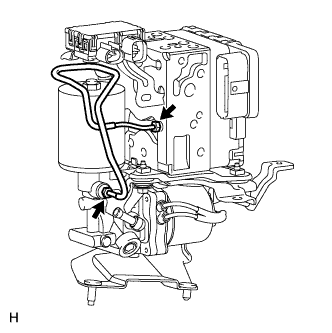
Using a union nut wrench, disconnect the No. 3 brake actuator tube.
-
-
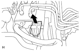
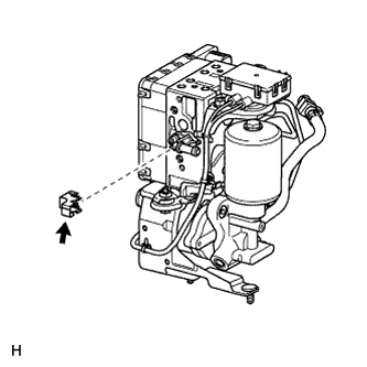
DISCONNECT BRAKE ACCUMULATOR PUMP CONNECTOR BOX
-
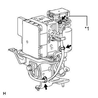
Text in Illustration *1 Connector Box Disconnect the brake accumulator pump connector box.
-
Detach the 2 wiring harness clamps.
-
Remove the nut and connector box.
-
-
-
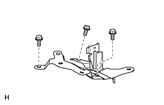
REMOVE NO. 4 BRAKE ACTUATOR BRACKET
-
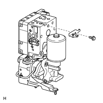
Remove the bolt and No. 4 brake actuator bracket.
-
-
REMOVE BRAKE ACCUMULATOR PUMP
-
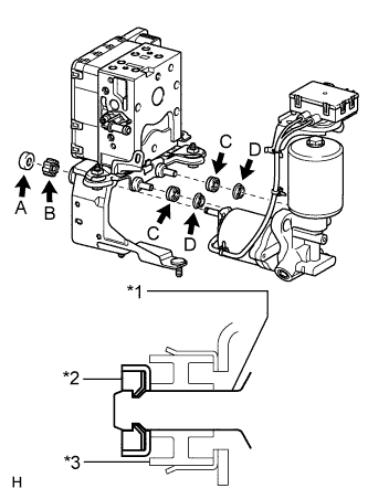
Text in Illustration *1 Brake Accumulator Pump *2 Clamp (A) *3 Bush (B) Break and remove the brake actuator bracket clamp (labeled A), and then remove the brake accumulator pump.
-
Remove the brake booster pump bush (labeled B) from the brake actuator bracket.
-
Remove the brake booster pump bushes (labeled C) and brake booster pump collars (labeled D) from the brake accumulator pump.
-
-
REMOVE BRAKE ACTUATOR
-
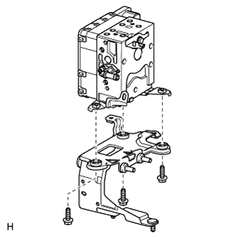
Remove the 3 bolts, brake actuator bracket and brake actuator.
-
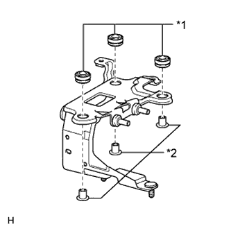
Text in Illustration *1 Cushion *2 Spacer Remove the 3 cushions and 3 spacers from the brake actuator bracket.
-
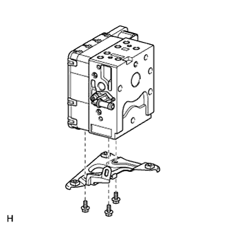
Remove the 3 bolts and No. 3 brake actuator bracket from the brake actuator.
-