STEERING ANGLE SENSOR REMOVAL

Note
While the battery is connected, even if the power switch is OFF, the brake control system activates when the brake pedal is depressed or the door courtesy switch turns on. Therefore during servicing of the brake system components, do not operate the brake pedal or open/close the doors while the battery is connected.
-
PRECAUTION
CAUTION:
Be sure to read the Precaution thoroughly before servicing Click here.
Note
After turning the power switch off, waiting time may be required before disconnecting the cable from the auxiliary battery terminal. Therefore, make sure to read the disconnecting the cable from the auxiliary battery terminal notice before proceeding with work Click here.
-
REMOVE LUGGAGE COMPARTMENT MAT SUB-ASSEMBLY (w/ Spare Tire)

-
REMOVE DECK BOARD ASSEMBLY (w/o Spare Tire)

-
REMOVE DECK TRIM SIDE BOARD LH (w/o Spare Tire)
-
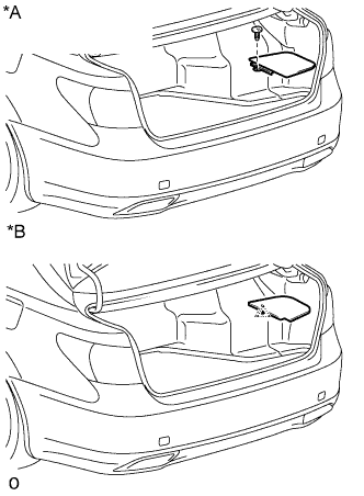
Text in Illustration *A w/ Spare Tire *B w/o Spare Tire w/ Spare Tire:
-
Remove the clip.
-
Remove the deck trim side board RH.
-
-
w/o Spare Tire:
-
Detach the clip and remove the deck trim side board RH.
-
-
-
REMOVE BATTERY SERVICE HOLE COVER LH
-

Text in Illustration *A for Standard *B for Ottoman *1 Fastening Tape Detach the clip, fastening tape and remove the battery service hole cover LH.
-
-
DISCONNECT CABLE FROM AUXILIARY BATTERY NEGATIVE TERMINAL
-
Disable the AUTO TILT AWAY function by changing the customize parameter Click here.
Note
Record the current customize parameter setting (whether the AUTO TILT AWAY function is enabled or disabled) in order to restore the current setting after finishing the operation.
-
Turn the power switch ON (IG). Operate the tilt and telescopic switch to fully extend and lower the steering column.
-
Turn the power switch OFF and disconnect the cable from the negative (-) battery terminal.
Note
When disconnecting the cable, some systems need to be initialized after the cable is reconnected Click here.
-
-
PLACE FRONT WHEELS FACING STRAIGHT AHEAD
-
REMOVE STEERING WHEEL ASSEMBLY
-
REMOVE STEERING COLUMN COVER
-
REMOVE SPIRAL CABLE SUB-ASSEMBLY
Note
-
Do not replace the spiral cable sub-assembly with the auxiliary battery connected and the power switch on (IG).
-
Do not rotate the spiral cable sub-assembly with the auxiliary battery connected and the power switch on (IG).
-
Ensure that the steering wheel is installed and aligned straight when inspecting the steering sensor.
-
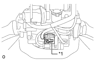
Text in Illustration *1 Slider Slide the slider to release the lock, and then disconnect the yellow airbag connector from the spiral cable sub-assembly with sensor.
Note
When handling the airbag connector, take care not to damage the airbag wire harness.
-
Disconnect the other connector from the spiral cable sub-assembly with sensor.
-
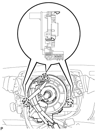
Detach the 3 claws to remove the spiral cable sub-assembly with sensor.
-
-
REMOVE STEERING SENSOR
-
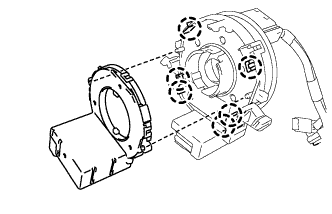
Detach the 6 claws and remove the steering sensor.
-