FRONT DOOR LOCK INSTALLATION

Tech Tips
-
Use the same procedures for the LH side and RH side.
-
The procedures listed below are for the LH side.
-
INSTALL FRONT DOOR INSIDE LOCKING CABLE ASSEMBLY LH
-
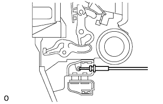
Install the front door inside locking cable assembly LH.
-
Attach the 3 claws.
-
-
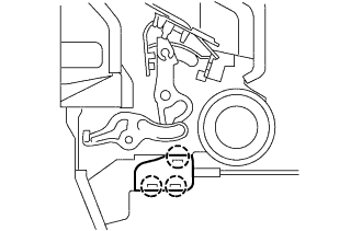
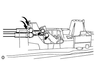
INSTALL FRONT DOOR LOCK REMOTE CONTROL CABLE ASSEMBLY LH
-
Install the front door lock remote control cable assembly LH.
-
Attach the claw.
-
-
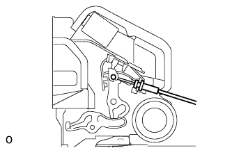
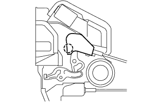
INSTALL FRONT DOOR LOCK ASSEMBLY LH
-
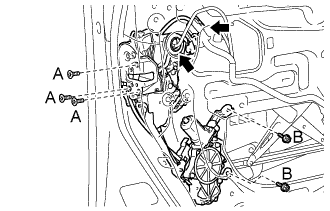
Apply adhesive to the threads of the 5 screws.
Adhesive Toyota Genuine Adhesive 1324, Three Bond 1324 or equivalent -
Install the front door lock assembly LH.
-
Using a T30 ''TORX'' wrench, install the 3 screws labeled A and the 2 screws labeled B.
- Torque:
- 5.5 N*m { 56 kgf*cm, 49 in.*lbf }
-
Connect the 2 connectors.
-
-
INSTALL FRONT DOOR LOWER FRAME GARNISH PAD LH
-
Install the front door lower frame garnish pad LH with the 2 bolts.
-
-
INSTALL FRONT DOOR OUTSIDE HANDLE COVER LH
-
Using a T30 ''TORX'' socket, install the front door outside handle cover LH (with the door key cylinder) with the screw.
- Torque:
- 4.0 N*m { 41 kgf*cm, 35 in.*lbf }
-
Install the hole plug.
-
-
INSTALL FRONT DOOR FRAME SUB-ASSEMBLY REAR LOWER LH
-
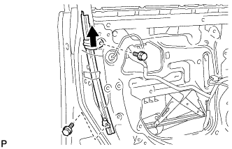
Install the front door rear lower frame sub-assembly LH with the 2 bolts.
- Torque:
- 8.0 N*m { 82 kgf*cm, 71 in.*lbf }
-
-
INSTALL FRONT DOOR GLASS SUB-ASSEMBLY LH
-
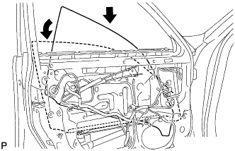
Insert the front door glass sub-assembly LH into the door panel along the glass run as indicated by the arrows in the illustration.
Note
Be careful not to damage the glass.
-
Install the front door glass sub-assembly LH to the front door window regulator sub-assembly LH with the 2 bolts.
- Torque:
- 5.5 N*m { 56 kgf*cm, 49 in.*lbf }
-
Install the hole plug.
-
-
INSTALL FRONT DOOR SERVICE HOLE COVER LH
-
Apply new butyl tape to the door.
-
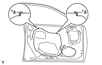
Text in Illustration *a Reference Point Install a new front door service hole cover LH using the reference points on the front door panel.
Tech Tips
-
When installing the service hole cover, pull the links and connectors through the service hole cover.
-
There should be no wrinkles or folds after attaching the service hole cover.
-
After attaching the service hole cover, check the sealing quality.
-
-
-
INSTALL FRONT DOOR TRIM COVER LH
-
Attach the 5 clips to install the front door trim cover LH.
-
Install the cushion.
-
-
INSTALL FRONT DOOR TRIM BOARD SUB-ASSEMBLY LH
-
Connect the connector.
-
Connect the 2 cables to the inside handle.
-
Attach the 13 clips to install the front door trim board sub-assembly LH.
-
Install the 3 screws.
-
-
INSTALL POWER WINDOW REGULATOR MASTER SWITCH ASSEMBLY WITH FRONT DOOR ARMREST BASE PANEL
-
Connect the connector.
-
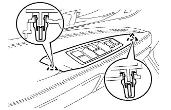
Attach the 2 claws to install the power window regulator master switch assembly with front door armrest base panel.
-
-
INSTALL DOOR INSIDE HANDLE BEZEL
-
Attach the 3 claws to install the front door inside handle bezel plug LH.
-
-
CONNECT CABLE TO AUXILIARY BATTERY NEGATIVE TERMINAL
Note
When disconnecting the cable, some systems need to be initialized after the cable is reconnected Click here.
-
INSTALL BATTERY SERVICE HOLE COVER LH
-

Text in Illustration *A for Standard *B for Ottoman Attach the battery service hole cover LH with the clip and fastening tape.
-
-
INSTALL DECK TRIM SIDE BOARD LH (w/o Spare Tire)
-

Attach the 2 clips to install the deck trim side board LH.
-
-
INSTALL DECK BOARD ASSEMBLY (w/o Spare Tire)

-
INSTALL LUGGAGE COMPARTMENT MAT SUB-ASSEMBLY (w/ Spare Tire)
