FRONT DOOR LOCK INSPECTION

-
INSPECT FRONT DOOR LOCK ASSEMBLY LH
-
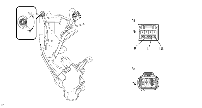
Apply battery voltage to the door lock motor and check operation of the door lock motor.
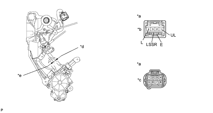
OK Measurement Condition Specified Condition Battery positive (+) → Terminal A4 (L)
Battery negative (-) → Terminal A1 (UL)
Lock Battery positive (+) → Terminal A1 (UL)
Battery negative (-) → Terminal A4 (L)
Unlock
-
If the result is not as specified, replace the front door lock assembly LH.
-
-
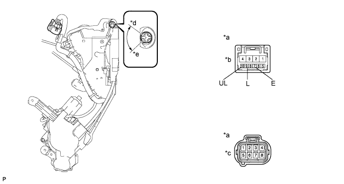
Measure the resistance of the door lock position switch.
Standard resistance Tester Connection Switch Condition Specified Condition A-7 (E) - A-8 (LSSR) Unlock Below 1 Ω A-7 (E) - A-8 (LSSR) Lock 10 kΩ or higher
-
If the result is not as specified, replace the front door lock assembly LH.
Text in Illustration *a Component without harness connected:
(Front Door Lock Assembly LH)
*b Connector A *c Connector B *d Unlock *e Lock -
-
Measure the resistance of the door lock and unlock switch.
Standard resistance Tester Connection Switch Condition Specified Condition A-9 (L) - A-7 (E) Lock Below 1 Ω A-10 (UL) - A-7 (E) Unlock Below 1 Ω A-9 (L) - A-7 (E) Unlock 10 kΩ or higher A-10 (UL) - A-7 (E) Lock 10 kΩ or higher
-
If the result is not as specified, replace the front door lock assembly LH.
Text in Illustration *a Component without harness connected:
(Front Door Lock Assembly LH)
*b Connector A *c Connector B *d Unlock *e Lock -
-
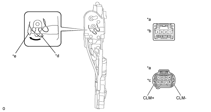
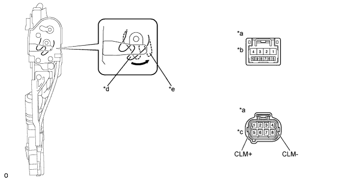
Closer motor operation inspection
-
Set the front door lock assembly LH to the half latch position.
-
When battery voltage is applied as shown below to the terminals of connector B of the front door lock assembly LH, check the operation of the door closer.
OK Measurement Condition Closer motor operation Battery positive (+) → Terminal B1 (CLM+)
Battery negative (-) → Terminal B4 (CLM-)
Moves to full latch position
-
If the result is not as specified, replace the front door lock assembly LH.
Text in Illustration *a Component without harness connected:
(Front Door Lock Assembly LH)
*b Connector A *c Connector B *d Half Latch *e Full Latch -
-
-
-
INSPECT FRONT DOOR LOCK ASSEMBLY RH
-
Apply battery voltage to the door lock motor and check operation of the door lock motor.
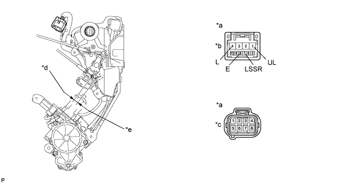
OK Measurement Condition Specified Condition Battery positive (+) → Terminal A4 (L)
Battery negative (-) → Terminal A1 (UL)
Lock Battery positive (+) → Terminal A1 (UL)
Battery negative (-) → Terminal A4 (L)
Unlock
-
If the result is not as specified, replace the front door lock assembly RH.
Text in Illustration *a Component without harness connected:
(Front Door Lock Assembly RH)
*b Connector A *c Connector B *d Unlock *e Lock -
-
Measure the resistance of the door lock position switch.
Standard resistance Tester Connection Switch Condition Specified Condition A-7 (LSSR) - A-8 (E) Unlock Below 1 Ω A-7 (LSSR) - A-8 (E) Lock 10 kΩ or higher
-
If the result is not as specified, replace the front door lock assembly RH.
-
-
Measure the resistance of the door lock and unlock switch.
Standard resistance Tester Connection Switch Condition Specified Condition A-5 (UL) - A-8 (E) Unlock Below 1 Ω A-6 (L) - A-8 (E) Lock Below 1 Ω A-5 (UL) - A-8 (E) Lock 10 kΩ or higher A-6 (L) - A-8 (E) Unlock 10 kΩ or higher
-
If the result is not as specified, replace the front door lock assembly RH.
Text in Illustration *a Component without harness connected:
(Front Door Lock Assembly RH)
*b Connector A *c Connector B *d Unlock *e Lock -
-
Closer motor operation inspection
-
Set the front door lock assembly RH to the half latch position.
-
When battery voltage is applied as shown below to the terminals of connector B of the front door lock assembly RH, check the operation of the door closer.
OK Measurement Condition Closer motor operation Battery positive (+) → Terminal B1 (CLM+)
Battery negative (-) → Terminal B4 (CLM-)
Moves to full latch position
-
If the result is not as specified, replace the front door lock assembly RH.
Text in Illustration *a Component without harness connected:
(Front Door Lock Assembly RH)
*b Connector A *c Connector B *d Half Latch *e Full Latch -
-
-