ELECTRONICALLY CONTROLLED BRAKE SYSTEM Brake Warning Light Remains ON
DESCRIPTION
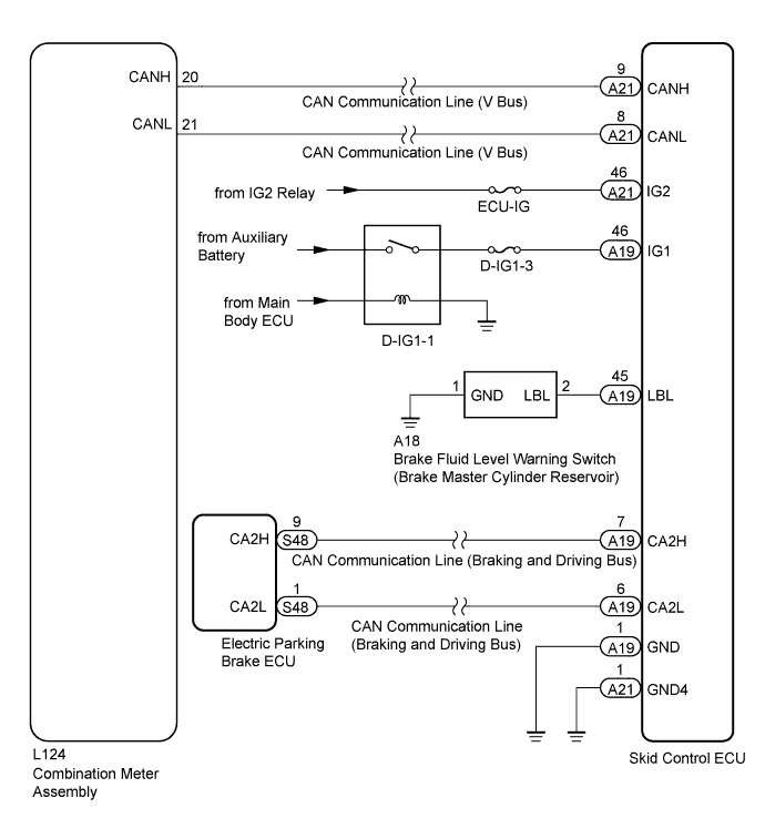
The skid control ECU is connected to the No. 1 meter ECU via CAN communication.
If any of the following is detected, the brake warning light / red (malfunction) remains on:
-
The skid control ECU connector is disconnected from the skid control ECU.
-
The brake fluid level is insufficient.
-
The EBD is defective.
Tech Tips
If the ABS warning light or brake warning light / yellow (minor malfunction) remains illuminated, return its condition to normal Click here or Click here.
WIRING DIAGRAM
INSPECTION PROCEDURE
Note
When replacing the skid control ECU, perform the following operations:
-
Initialization of linear solenoid valve and calibration Click here
-
Yaw rate and acceleration sensor zero point calibration Click here
PROCEDURE
-
CHECK DTC
-
Check if the ABS, VSC and/or electronically controlled brake system DTC is output Click here.
Result Result Proceed to DTC is not output A DTC is output B
B 
REPAIR CIRCUIT INDICATED BY OUTPUT CODE Click here
A 
-
-
INSPECT CAN COMMUNICATION SYSTEM
-
for LHD:
Check if the CAN communication system DTC is output Click here.
for RHD:
Check if the CAN communication system DTC is output Click here.
Result Result Proceed to DTC is not output A DTC is output for LHD B for RHD C
B
GO TO CAN COMMUNICATION SYSTEM (HOW TO PROCEED WITH TROUBLESHOOTING) Click here
C
GO TO CAN COMMUNICATION SYSTEM (HOW TO PROCEED WITH TROUBLESHOOTING) Click here
A
-
-
INSPECT IF SKID CONTROL ECU CONNECTOR IS SECURELY CONNECTED
-
Check the skid control ECU connector's connection.
OK The connector is securely connected.
NG
CONNECT CONNECTOR TO ECU CORRECTLY
OK
-
-
INSPECT BATTERY
-
Check the battery voltage.
Standard voltage 11 to 14 V
NG
RECHARGE OR REPLACE BATTERY Click here
OK
-
-
CHECK TERMINAL VOLTAGE (IG1, IG2)
-
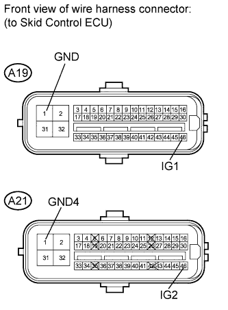
Disconnect the A19 and A21 ECU connectors.
-
Turn the power switch ON (IG).
-
Measure the voltage according to the value(s) in the table below.
Standard voltage Tester Connection Switch Condition Specified Condition A19-46 (IG1) - A19-1 (GND) Power switch ON (IG) 11 to 14 V A21-46 (IG2) - A21-1 (GND4) Power switch ON (IG) 11 to 14 V -
Measure the resistance according to the value(s) in the table below.
Standard resistance Tester Connection Condition Specified Condition A19-1 (GND) - Body ground Always Below 1 Ω A21-1 (GND4) - Body ground Always Below 1 Ω
NG
REPAIR OR REPLACE HARNESS OR CONNECTOR
OK
-
-
INSPECT COMBINATION METER ASSEMBLY
-
Perform the meter and gauge system active test Click here.
Tech Tips
If troubleshooting has been carried out according to the PROBLEM SYMPTOMS TABLE, refer back to the table and proceed to the next step before replacing the part Click here.
Result Result Proceed to NG A OK for LHD B for RHD C
B
REPLACE SKID CONTROL ECU Click here
C
REPLACE SKID CONTROL ECU Click here
A 
REPLACE NO. 1 METER ECU SUB-ASSEMBLY Click here
-