ELECTRONICALLY CONTROLLED BRAKE SYSTEM TC and CG Terminal Circuit
DESCRIPTION
Connecting terminals TC and CG of the DLC3 causes the ECU to display the DTC by blinking the ABS warning light, brake warning light / yellow (minor malfunction), slip indicator light and/or brake hold stand by indicator light.
WIRING DIAGRAM
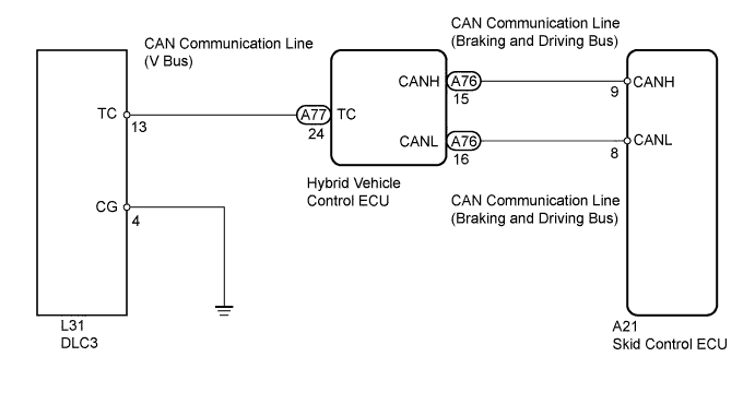
INSPECTION PROCEDURE
Note
When replacing the skid control ECU, perform the following operations:
-
Initialization of linear solenoid valve and calibration Click here.
-
Yaw rate and acceleration sensor zero point calibration Click here.
PROCEDURE
-
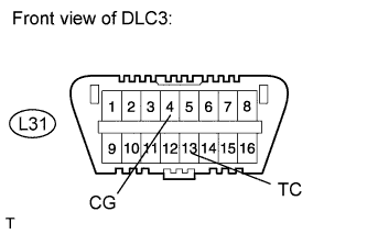
INSPECT DLC3 (TC AND CG TERMINAL)
-
Turn the power switch ON (IG).
-
Measure the voltage according to the value(s) in the table below.
Standard voltage Tester Connection Switch Condition Specified Condition L31-13 (TC) - Body ground Power switch ON (IG) 11 to 14 V -
Measure the resistance according to the value(s) in the table below.
Standard resistance Tester Connection Condition Specified Condition L31-4 (CG) - Body ground Always Below 1 Ω
NG 
CHECK HARNESS AND CONNECTOR (DLC3 - HYBRID VEHICLE CONTROL ECU) Click here
OK 
-
-
CHECK CAN COMMUNICATION SYSTEM
-
for LHD:
Check if the CAN communication system DTC is output Click here.
for RHD:
Check if the CAN communication system DTC is output Click here.
Result Result Proceed to DTC is not output A DTC is output for LHD B for RHD C Tech Tips
If troubleshooting has been carried out according to the "PROBLEM SYMPTOMS TABLE", refer back to the table and proceed to the next step before replacing the part Click here.
B 
GO TO CAN COMMUNICATION SYSTEM (HOW TO PROCEED WITH TROUBLESHOOTING) Click here
C
GO TO CAN COMMUNICATION SYSTEM (HOW TO PROCEED WITH TROUBLESHOOTING) Click here
A
-
-
CHECK HARNESS AND CONNECTOR (DLC3 - HYBRID VEHICLE CONTROL ECU)
-
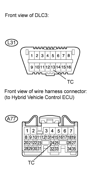
Disconnect the A77 ECU connector.
-
Measure the resistance according to the value(s) in the table below.
Standard resistance Tester Connection Condition Specified Condition L31-13 (TC) - A77-24 (TC) Always Below 1 Ω L31-13 (TC) - Body ground Always 10 kΩ or higher
NG
REPAIR OR REPLACE HARNESS OR CONNECTOR
OK
-
-
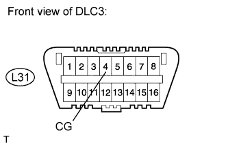
CHECK HARNESS AND CONNECTOR (DLC3 - BODY GROUND)
-
Measure the resistance according to the value(s) in the table below.
Standard resistance Tester Connection Condition Specified Condition L31-4 (CG) - Body ground Always Below 1 Ω
NG
REPAIR OR REPLACE HARNESS OR CONNECTOR
OK
-
-
CHECK HYBRID VEHICLE CONTROL ECU (DLC3 INPUT)
-
Using SST, connect terminals 13 (TC) and 4 (CG) of the DLC3.
- SST
- 09843-18040
-
Check if the ABS warning light is blinking.
Result Result Proceed to ABS warning light is blinking A ABS warning light is not blinking B
B
REPLACE HYBRID VEHICLE CONTROL ECU Click here
A
-
-
CHECK CAN COMMUNICATION SYSTEM
-
for LHD:
Check if the CAN communication system DTC is output Click here.
for RHD:
Check if the CAN communication system DTC is output Click here.
Result Result Proceed to DTC is not output for LHD A for RHD B DTC is output for LHD C for RHD D Tech Tips
If troubleshooting has been carried out according to the "PROBLEM SYMPTOMS TABLE", refer back to the table and proceed to the next step before replacing the part Click here.
B
REPLACE SKID CONTROL ECU Click here
C
GO TO CAN COMMUNICATION SYSTEM (HOW TO PROCEED WITH TROUBLESHOOTING) Click here
D
GO TO CAN COMMUNICATION SYSTEM (HOW TO PROCEED WITH TROUBLESHOOTING) Click here
A 
REPLACE SKID CONTROL ECU Click here
-