ELECTRONICALLY CONTROLLED BRAKE SYSTEM, Diagnostic DTC:C1378/44

| DTC Code | DTC Name |
|---|---|
| C1378/44 | Capacitor Communication Malfunction |
DESCRIPTION
Refer to DTC C1377/43 Click here.
| DTC Code | Information Code | DTC Detection Condition | Trouble Area |
|---|---|---|---|
| C1378/44 | 112 | When one of the following is detected:
|
|
WIRING DIAGRAM
Refer to DTC C1377/43 Click here.
INSPECTION PROCEDURE
Note
When replacing the skid control ECU, perform the following operations:
-
Initialization of linear solenoid valve and calibration Click here
-
Yaw rate and acceleration sensor zero point calibration Click here
PROCEDURE
-
CHECK TERMINAL VOLTAGE AND RESISTANCE (IG, GND)
-
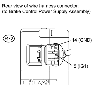
Disconnect the R72 power supply connector.
-
Measure the voltage according to the value(s) in the table below.
Standard voltage Tester Connection Switch Condition Specified Condition R72-5 (IG1) - Body ground Power switch ON (IG) 11 to 14 V -
Measure the resistance according to the value(s) in the table below.
Standard resistance Tester Connection Condition Specified Condition R72-14 (GND) - Body ground Always Below 1 Ω
NG 
REPAIR OR REPLACE HARNESS OR CONNECTOR
OK 
-
-
CHECK HARNESS AND CONNECTOR (SKID CONTROL ECU - BRAKE CONTROL POWER SUPPLY ASSEMBLY)
-
Disconnect the A19 and A21 ECU connectors.
-
Disconnect the R72 power supply connector.
-
Measure the resistance according to the value(s) in the table below.
Standard resistance Tester Connection Condition Specified Condition A19-8 (ENA) - R72-12 (ENA) Always Below 1 Ω A21-41 (FAIL) - R72-13 (FAIL) Always Below 1 Ω A19-8 (ENA) - Body ground Always 10 kΩ or higher A21-41 (FAIL) - Body ground Always 10 kΩ or higher
NG
REPAIR OR REPLACE HARNESS OR CONNECTOR
OK
-
-
RECONFIRM DTC
-
Clear the DTC Click here.
-
Turn the power switch ON (IG).
-
Check if the same DTC is recorded Click here.
Tech Tips
Reinstall the sensor, connectors, etc. and restore the vehicle to its prior condition before rechecking for DTCs.
Result Result Proceed to DTC (C1378/44) is output A DTC (C1378/44) is not output B
B
USE SIMULATION METHOD TO CHECK Click here
A
-
-
CHECK FREEZE FRAME DATA
-
Check the information code from the "FREEZE FRAME DATA" memorized when the DTC (C1378/44) is stored Click here.
Result Result Proceed to Information code (112) is output A Information code is not output for LHD B for RHD C
B
REPLACE SKID CONTROL ECU Click here
C
REPLACE SKID CONTROL ECU Click here
A 
REPLACE BRAKE CONTROL POWER SUPPLY ASSEMBLY Click here
-