ELECTRONICALLY CONTROLLED BRAKE SYSTEM VSC OFF Indicator Light Remains ON
DESCRIPTION
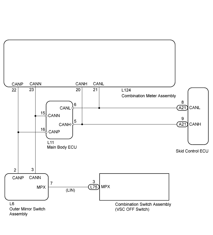
The skid control ECU is connected to the combination meter via CAN communication.
The VSC OFF indicator light illuminates to inform the driver when VSC OFF mode is entered using the VSC OFF switch.
WIRING DIAGRAM
INSPECTION PROCEDURE
Note
When replacing the skid control ECU, perform initialization of the linear solenoid valve and calibration Click here.
PROCEDURE
-
PREPARE FOR INSPECTION
-
Check that both of the following conditions are satisfied.
-
The vehicle is not in VSC OFF mode.
-
The vehicle is not in inspection mode.
Tech Tips
Confirm if the vehicle is in inspection mode or not by using the intelligent tester Data List.
-
NEXT 
-
-
INSPECT CAN COMMUNICATION SYSTEM
-
for LHD:
Check if a CAN communication system DTC is output Click here.
for RHD:
Check if a CAN communication system DTC is output Click here.
Result Result Proceed to DTC is not output A DTC is output for LHD B for RHD C
B 
GO TO CAN COMMUNICATION SYSTEM Click here
C
GO TO CAN COMMUNICATION SYSTEM Click here
A
-
-
INSPECT SKID CONTROL ECU CONNECTOR
-
Check if the skid control ECU connector is securely connected.
OK The connector is securely connected.
NG
CONNECT CONNECTOR CORRECTLY
OK
-
-
INSPECT COMBINATION METER ASSEMBLY
-
Inspect the combination meter Click here.
Result Result Proceed to NG A OK for LHD B for RHD C
B
REPLACE SKID CONTROL ECU Click here
C
REPLACE SKID CONTROL ECU Click here
A 
REPLACE NO. 1 METER ECU SUB-ASSEMBLY Click here
-