ELECTRONICALLY CONTROLLED BRAKE SYSTEM, Diagnostic DTC:C1256/57

| DTC Code | DTC Name |
|---|---|
| C1256/57 | Accumulator Low Pressure |
DESCRIPTION
The accumulator pressure sensor is built into the actuator and detects the accumulator pressure.
The skid control ECU turns on the brake warning light / yellow (minor malfunction) and sounds the skid control buzzer if it senses a decrease in the accumulator pressure.
Tech Tips
DTC C1256/57 may be output if the accumulator pressure drops due to frequent braking (this is not a malfunction).
| DTC Code | Information Code | DTC Detection Condition | Trouble Area |
|---|---|---|---|
| C1256/57 | 141 | When either of the following is detected (after a condition is met, the code is stored and the buzzer sounds):
|
|
| ↑ | 143 | When any of the following is detected:
|
↑ |
WIRING DIAGRAM
Refer to DTCs C1252/52 and C1253/53 Click here.
INSPECTION PROCEDURE
Note
When replacing the brake actuator, perform initialization of the linear solenoid valve and calibration Click here.
Tech Tips
When C1202/68, C1241/41, C1252/52, C1253/53 or C1391/69 are output together with C1256/57, inspect and repair the trouble areas indicated by C1202/68, C1241/41, C1252/52, C1253/53 or C1391/69 first.
PROCEDURE
-
CONFIRM DTC
-
Confirm output DTCs Click here.
Result Result Proceed to DTC C1256 is output A DTC C1241, C1252, C1253, C1202 or C1391 is output B
B 
CHECK CIRCUIT INDICATED BY OUTPUT DTC Click here
A 
-
-
CUSTOMER PROBLEM ANALYSIS
-
Perform customer problem analysis to confirm whether if the customer was frequently braking when the brake warning light/yellow (minor malfunction) was illuminated.
Tech Tips
DTC C1256/57 may be output if the accumulator pressure drops due to frequent braking (this is not a malfunction).
Result Result Proceed to There was no frequent braking A There was frequent braking B
B 
READ VALUE USING INTELLIGENT TESTER (ACCUMULATOR PRESSURE SENSOR) Click here
A
-
-
INSPECT BRAKE ACCUMULATOR PUMP
-
Turn the power switch OFF.
-
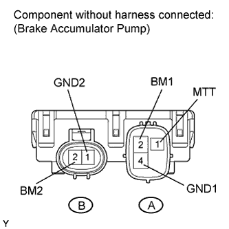
Disconnect the A23 and A24 accumulator connectors.
-
Measure the resistance according to the value(s) in the table below.
Standard resistance Tester Connection Condition Specified Condition A2 (BM1) - A4 (GND1) Always 10 Ω or less B2 (BM2) - A4 (GND1) A2 (BM1) - B2 (BM2) Always Below 1 Ω A4 (GND1) - B1 (GND2) A2 (BM1) - A1 (MTT) Always 950 to 1050 Ω B2 (BM2) - A1 (MTT) Result Result Proceed to OK A NG for LHD B for RHD C
B
REPLACE BRAKE ACCUMULATOR PUMP Click here
C
REPLACE BRAKE ACCUMULATOR PUMP Click here
A
-
-
READ VALUE USING INTELLIGENT TESTER (ACCUMULATOR PRESSURE SENSOR)
-
Connect the intelligent tester to the DLC3.
-
Turn the power switch ON (IG).
-
Select the DATA LIST mode on the intelligent tester.
ABS/VSC/TRAC: Tester Display Measurement Item /Range Normal Condition Diagnostic Note Accumulator Pressure Sensor Accumulator pressure sensor / min.: 0 V, max.: 5 V Specified value: 2.6 to 3.8 V - -
Depress the brake pedal 4 or 5 times to operate the pump motor, and check the output value on the intelligent tester with the motor stopped (not braking) for 30 seconds.
OK The accumulator pressure sensor voltage change is within 0.2 V.
NG
PERFORM ACTIVE TEST USING INTELLIGENT TESTER (SMC1, SMC2, SLRRR, AND SLRRL) Click here
OK 
USE SIMULATION METHOD TO CHECK Click here
-
-
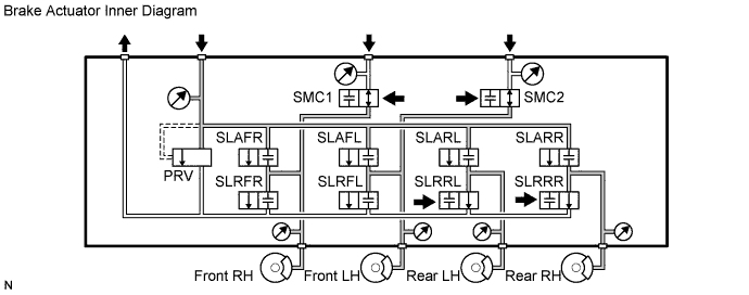
PERFORM ACTIVE TEST USING INTELLIGENT TESTER (SMC1, SMC2, SLRRR, AND SLRRL)
-
Connect the intelligent tester to the DLC3.
-
Turn the power switch ON (IG).
-
Select the ACTIVE TEST mode on the intelligent tester.
ABS/VSC/TRAC: Tester Display Test Part Control Range Diagnostic Note Electronically Controlled Brake System Solenoid (SMC1) Turns electronically controlled brake system solenoid (SMC1) ON / OFF Operation sound of solenoid (clicking sound) can be heard Electronically Controlled Brake System Solenoid (SMC2) Turns electronically controlled brake system solenoid (SMC2) ON / OFF Operation sound of solenoid (clicking sound) can be heard Electronically Controlled Brake System Solenoid (SLRRR) Valve Close Turns SLRRR solenoid ON / OFF Operation sound of solenoid (clicking sound) can be heard Electronically Controlled Brake System Solenoid (SLRRL) Valve Close Turns SLRRL solenoid ON / OFF Operation sound of solenoid (clicking sound) can be heard -
Using the intelligent tester, turn SMC1, SMC2, SLRRR, or SLRRL ON.
-
Check that each wheel cylinder's output value does not increase.
OK Each wheel cylinder's output value does not increase. Tech Tips
If any of wheel cylinder's output value increases, there may be a brake fluid leak in the brake actuator.
Result Result Proceed to OK for LHD A for RHD B NG for LHD C for RHD D
B
REPLACE BRAKE ACCUMULATOR PUMP Click here
C
REPLACE BRAKE ACTUATOR Click here
D
REPLACE BRAKE ACTUATOR Click here
A
REPLACE BRAKE ACCUMULATOR PUMP Click here
-