ELECTRONICALLY CONTROLLED BRAKE SYSTEM, Diagnostic DTC:C1252/52, C1253/53

| DTC Code | DTC Name |
|---|---|
| C1252/52 | Brake Booster Pump Motor on Time Abnormally Long |
| C1253/53 | Pump Motor Relay Malfunction |
DESCRIPTION
The skid control ECU detects decreases in the accumulator pressure according to the data from the accumulator pressure sensor, and then starts and stops the pump motor by operating the motor relay.
The skid control ECU usually drives the ABS motor relay (ABS MTR) for electronically controlled brake system control, and the ABS motor relay 2 (ABS MTR2) for ABS control. If either is of them malfunctioning, the other will substitute.
| DTC Code | Information Code | DTC Detection Condition | Trouble Area |
|---|---|---|---|
| C1252/52 | 130 | Motor relay is on for at least 3 minutes. |
|
| C1253/53 | 134 | When the linear solenoid power supply 1 (BS1) is 9.5 V or more, either of +BI1 or +BI2 voltage is 7 V or more, and the motor relay 1 is on, MTT input of less than 3.5 V continues for 1 second or more. |
|
| ↑ | 138 | When the linear solenoid power supply 2 (BS2) is 9.5 V or more, either of +BI1 or +BI2 voltage is 7 V or more, and the motor relay 2 is on, MTT input of less than 3.5 V continues for 1 second or more. |
|
| ↑ | 140 | MTT input is 3.5 V or more for at least 2 seconds when motor relay 1 and 2 are off. |
|
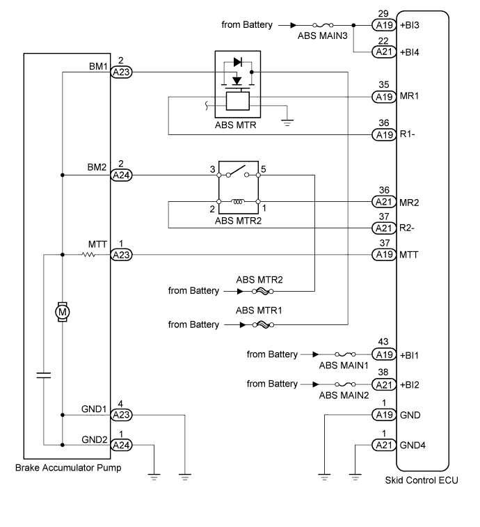
WIRING DIAGRAM
INSPECTION PROCEDURE
Note
-
When replacing the skid control ECU, perform the following operations:
-
Initialization of linear solenoid valve and calibration Click here
-
Yaw rate and acceleration sensor zero point calibration Click here
-
When replacing the brake actuator, perform initialization of the linear solenoid valve and calibration Click here.
PROCEDURE
-
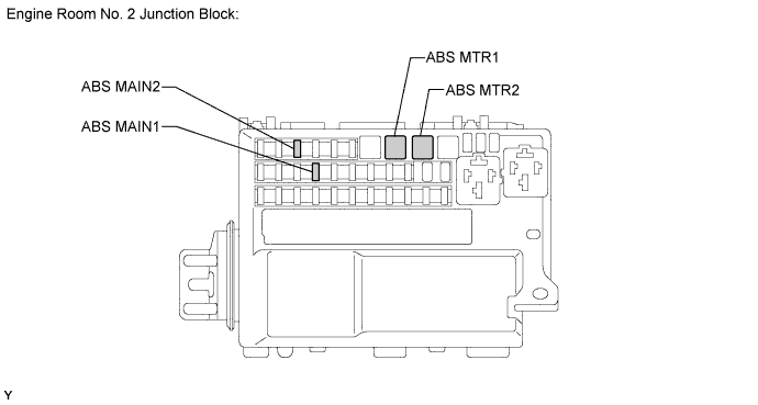
INSPECT FUSE (ABS MTR1, ABS MTR2, ABS MAIN1 AND ABS MAIN2)
-
Remove the ABS MTR1, ABS MTR2, ABS MAIN1 and ABS MAIN2 fuses from the engine room No. 2 junction block.
-
Measure the resistance of the fuses.
Standard resistance Tester Connection Condition Specified Condition ABS MTR1 H-fuse Always Below 1 Ω ABS MTR2 H-fuse Always Below 1 Ω ABS MAIN1 Always Below 1 Ω ABS MAIN2 Always Below 1 Ω
NG 
REPLACE FUSE
OK 
-
-
PERFORM ACTIVE TEST USING INTELLIGENT TESTER (ABS MTR1 RELAY)
-
Connect the intelligent tester to the DLC3.
-
Turn the power switch ON (IG).
-
Select the ACTIVE TEST mode on the intelligent tester.
Tech Tips
-
The ABS motor relay (ABS MTR) is a semiconductor relay. It does not emit operation sounds.
-
The ABS motor relay (ABS MTR) cannot be removed and inspected, as it is part of the engine room No. 2 relay block.
ABS/VSC/TRAC: Tester Display Test Part Control Range Diagnostic Note Electronically Controlled Brake System Motor Relay Turns electronically controlled brake system motor relay ON / OFF Operation sound of motor can be heard -
-
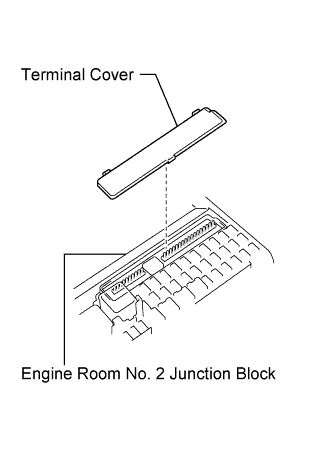
Remove the terminal cover.
-
Measure the voltage according to the value(s) in the table below.
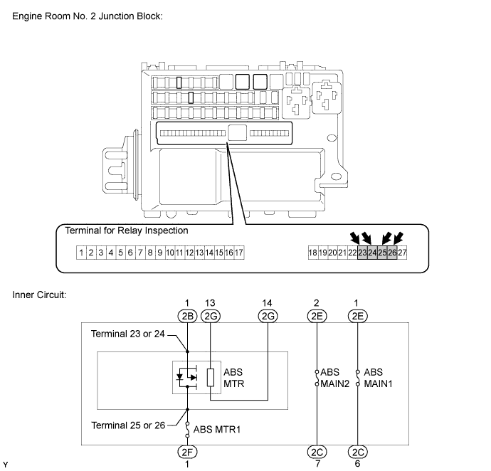
Standard voltage Tester Connection Switch Condition Specified Condition Terminal 23 or 24 - Body ground ABS MTR relay: ON 11 to 14 V ABS MTR relay: OFF Below 1 V Terminal 25 or 26 - Body ground Always 11 to 14 V
NG 
CHECK HARNESS AND CONNECTOR (ENGINE ROOM NO. 2 JUNCTION BLOCK - BATTERY) Click here
OK
-
-
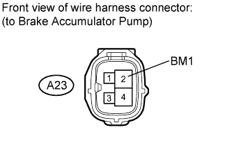
CHECK HARNESS AND CONNECTOR (BRAKE ACCUMULATOR PUMP - ENGINE ROOM NO. 2 JUNCTION BLOCK)
-
Disconnect the A23 pump connector.
-
Read value of intelligent tester (ABS MTR relay).
-
Connect the intelligent tester to the DLC3.
-
Turn the power switch ON (IG).
-
Select the ACTIVE TEST mode on the intelligent tester.
ABS/VSC/TRAC: Tester Display Test Part Control Range Diagnostic Note Electronically Controlled Brake System Motor Relay Turns electronically controlled brake system motor relay ON / OFF Operation sound of relay (clicking sound) and motor can be heard
-
-
Measure the voltage according to the value(s) in the table below.
Standard voltage Tester Connection Switch Condition Specified Condition A23-2 (BM1) - Body ground ABS MTR relay: ON 11 to 14 V ABS MTR relay: OFF Below 1 V
NG
REPAIR OR REPLACE HARNESS OR CONNECTOR
OK
-
-
READ VALUE USING INTELLIGENT TESTER (ABS MTR2 RELAY)
-
Connect the intelligent tester to the DLC3.
-
Turn the power switch ON (IG).
-
Select the ACTIVE TEST mode on the intelligent tester.
ABS/VSC/TRAC: Tester Display Test Part Control Range Diagnostic Note Electronically Controlled Brake System Motor Relay 2 Turns electronically controlled brake system motor relay 2 ON / OFF Operation sound of relay (clicking sound) and motor can be heard -
Check the operation sound of the ABS motor relay 2 (ABS MTR2) and motor when operating it with the intelligent tester.
OK The operation sound of the ABS motor relay 2 (ABS MTR2) and motor are heard.
NG
INSPECT ABS MOTOR RELAY 2 (ABS MTR2) Click here
OK
-
-
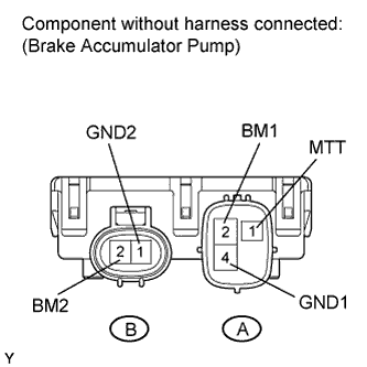
INSPECT BRAKE ACCUMULATOR PUMP
-
Turn the power switch OFF.
-
Disconnect the A23 and A24 pump connectors.
-
Measure the resistance according to the value(s) in the table below.
Standard resistance Tester Connection Condition Specified Condition A-2 (BM1) - A-4 (GND1) Always 10 Ω or less B-2 (BM2) - A-4 (GND1) A-2 (BM1) - B-2 (BM2) Always Below 1 Ω A-4 (GND1) - B-1 (GND2) A-2 (BM1) - A-1 (MTT) Always 950 to 1050 Ω B-2 (BM2) - A-1 (MTT) Result Result Proceed to OK A NG for LHD B for RHD C
B
REPLACE BRAKE ACCUMULATOR PUMP Click here
C
REPLACE BRAKE ACCUMULATOR PUMP Click here
A
-
-
CHECK HARNESS AND CONNECTOR (SKID CONTROL ECU - BRAKE ACCUMULATOR PUMP)
-
Turn the power switch OFF.
-
Disconnect the A19 ECU connector.
-
Disconnect the A23 and A24 pump connectors.
-
Measure the resistance according to the value(s) in the table below.
Standard resistance Tester Connection Condition Specified Condition A19-37 (MTT) - A23-1 (MTT) Always Below 1 Ω A19-37 (MTT) - Body ground Always 10 kΩ or higher A23-4 (GND1) - Body ground Always Below 1 Ω A24-1 (GND2) - Body ground Always Below 1 Ω
NG
REPAIR OR REPLACE HARNESS OR CONNECTOR
OK
-
-
READ VALUE USING INTELLIGENT TESTER (ACCUMULATOR PRESSURE SENSOR)
-
Connect the intelligent tester to the DLC3.
-
Turn the power switch ON (IG).
-
Select the DATA LIST mode on the intelligent tester.
ABS/VSC/TRAC: Tester Display Measurement Item /
Range
Normal Condition Diagnostic Note Accumulator Pressure Sensor Accumulator pressure sensor / min.: 0 V, max.: 5 V Specified value: 2.6 to 3.8 V - -
Depress the brake pedal 4 or 5 times to operate the pump motor, and check the output value on the intelligent tester with the motor stopped (not braking) for 30 seconds.
OK The accumulator pressure sensor voltage change is within 0.2 V. Tech Tips
-
This inspection is performed to determine if there is a long term power malfunction when low pressure is detected in the accumulator due to a sensor malfunction, fluid leak in the actuator, or accumulator deterioration.
-
If the reservoir fluid level drops, there may be a fluid leak.
-
NG
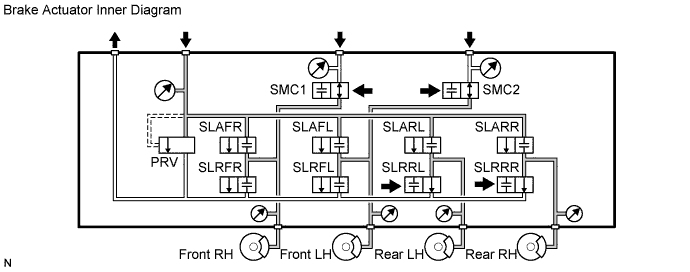
PERFORM ACTIVE TEST USING INTELLIGENT TESTER (SMC1, SMC2, SLRRR, AND SLRRL) Click here
OK
-
-
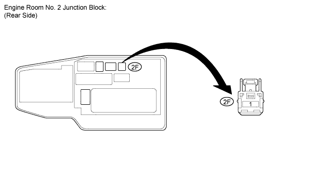
CHECK HARNESS AND CONNECTOR (ENGINE ROOM NO. 2 JUNCTION BLOCK - BATTERY)
-
Disconnect the 2F junction block connector.
-
Measure the voltage according to the value(s) in the table below.
Standard voltage Tester Connection Condition Specified Condition 2F-1 - Body ground Always 11 to 14 V
NG
REPAIR OR REPLACE HARNESS OR CONNECTOR
OK
-
-
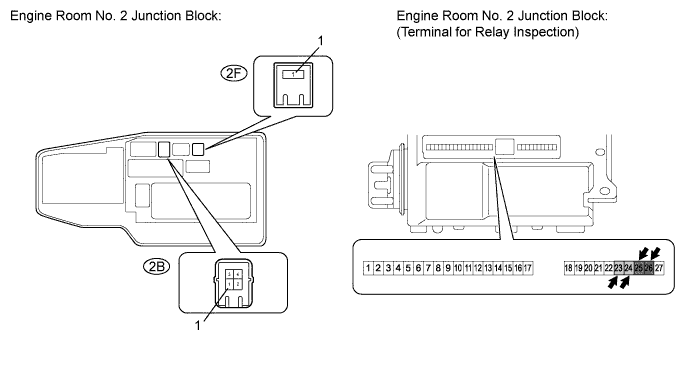
INSPECT ENGINE ROOM NO. 2 JUNCTION BLOCK (INNER CIRCUIT)
-
Turn the power switch OFF.
-
Disconnect the 2B and 2F junction block connectors.
-
Measure the resistance according to the value(s) in the table below.
Standard resistance Tester Connection Condition Specified Condition 2F-1 - Terminal 25 or 26 Always Below 1 Ω 2B-1 - Terminal 23 or 24 Always Below 1 Ω
NG
REPLACE ENGINE ROOM NO. 2 JUNCTION BLOCK AND/OR NO. 2 RELAY BLOCK Click here
OK
-
-
CHECK HARNESS AND CONNECTOR (SKID CONTROL ECU - ENGINE ROOM NO. 2 JUNCTION BLOCK)
-
Turn the power switch OFF.
-
Disconnect the A19 ECU connector.
-
Disconnect the 2G junction block connector.
-
Measure the resistance according to the value(s) in the table below.
Standard resistance Tester Connection Condition Specified Condition A19-35 (MR1) - 2G-14 Always Below 1 Ω A19-36 (R1-) - 2G-13 Always Below 1 Ω A19-35 (MR1) - Body ground Always 10 kΩ or higher A19-36 (R1-) - Body ground Always 10 kΩ or higher
NG
REPAIR OR REPLACE HARNESS OR CONNECTOR
OK 
REPLACE ENGINE ROOM NO. 2 JUNCTION BLOCK Click here
-
-
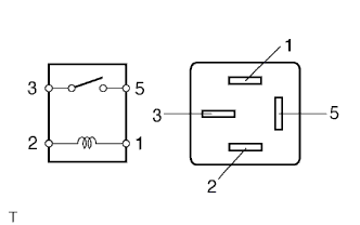
INSPECT ABS MOTOR RELAY 2 (ABS MTR2)
-
Remove the ABS motor relay 2 (ABS MTR2).
-
Measure the resistance according to the value(s) in the table below.
Standard resistance Tester Connection Condition Specified Condition 3 - 5 When battery voltage is not applied to terminals 1 and 2 10 kΩ or higher 3 - 5 When battery voltage is applied to terminals 1 and 2 Below 1 Ω
NG
REPLACE ABS MOTOR RELAY 2 (ABS MTR2) Click here
OK
-
-
CHECK TERMINAL VOLTAGE (NO. 3 RELAY BLOCK)
-
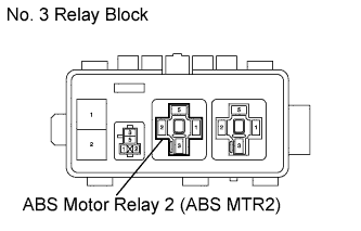
Remove the ABS motor relay 2 (ABS MTR2).
-
Measure the voltage according to the value(s) in the table below.
Standard voltage Tester Connection Condition Specified Condition ABS motor relay 2 (ABS MTR2) terminal 5 - Body ground Always 11 to 14 V
NG
REPAIR OR REPLACE HARNESS OR CONNECTOR
OK
-
-
CHECK HARNESS AND CONNECTOR (BRAKE ACCUMULATOR PUMP - NO. 3 RELAY BLOCK)
-
Disconnect the A24 pump connector.
-
Remove the ABS motor relay 2 (ABS MTR2).
-
Measure the resistance according to the value(s) in the table below.
Standard resistance Tester Connection Condition Specified Condition A24-2 (BM2) - ABS motor relay 2 (ABS MTR2) terminal 3 Always Below 1 Ω A24-2 (BM2) - Body ground Always 10 kΩ or higher
NG
REPAIR OR REPLACE HARNESS OR CONNECTOR
OK
-
-
CHECK HARNESS AND CONNECTOR (SKID CONTROL ECU - NO. 3 RELAY BLOCK)
-
Disconnect the A21 ECU connector.
-
Remove the ABS motor relay 2 (ABS MTR2).
-
Measure the resistance according to the value(s) in the table below.
Standard resistance Tester Connection Condition Specified Condition A21-36 (MR2) - ABS motor relay 2 (ABS MTR2) terminal 1 Always Below 1 Ω A21-37 (R2-) - ABS motor relay 2 (ABS MTR2) terminal 2 Always Below 1 Ω A21-37 (R2-) - Body ground Always 10 kΩ or higher A21-36 (MR2) - Body ground Always 10 kΩ or higher
NG
REPAIR OR REPLACE HARNESS OR CONNECTOR
OK
-
-
RECONFIRM DTC
-
Clear the DTC Click here.
-
Turn the power switch ON (IG).
-
Check if the same DTCs are recorded Click here.
Tech Tips
Reinstall the sensors, connectors, etc. and restore the vehicle to its prior condition before rechecking for DTCs.
Result Result Proceed to DTCs (C1252/52 and C1253/53) are not output A DTCs (C1252/52 and C1253/53) are output for LHD B for RHD C
B
REPLACE SKID CONTROL ECU Click here
C
REPLACE SKID CONTROL ECU Click here
A
USE SIMULATION METHOD TO CHECK Click here
-
-
PERFORM ACTIVE TEST USING INTELLIGENT TESTER (SMC1, SMC2, SLRRR, AND SLRRL)
-
Connect the intelligent tester to the DLC3.
-
Turn the power switch ON (IG).
-
Select the ACTIVE TEST mode on the intelligent tester.
Tech Tips
The ACTIVE TEST can be performed when the following conditions are met.
-
Main relay 1 and 2 are on.
-
Shift lever is P position.
-
Parking brake is on.
-
Vehicle speed is 0 km/h (0 mph).
ABS/VSC/TRAC: Tester Display Test Part Control Range Diagnostic Note Electronically Controlled Brake System Solenoid (SMC1) Turns electronically controlled brake system solenoid (SMC1) ON / OFF Operation sound of solenoid (clicking sound) can be heard Electronically Controlled Brake System Solenoid (SMC2) Turns electronically controlled brake system solenoid (SMC2) ON / OFF Operation sound of solenoid (clicking sound) can be heard Electronically Controlled Brake System Solenoid (SLRRR) Valve Close Turns SLRRR solenoid ON / OFF Operation sound of solenoid (clicking sound) can be heard Electronically Controlled Brake System Solenoid (SLRRL) Valve Close Turns SLRRL solenoid ON / OFF Operation sound of solenoid (clicking sound) can be heard -
-
Using the intelligent tester, turn SMC1, SMC2, SLRRR, or SLRRL ON.
-
Check that each wheel cylinder's output value does not increase.
OK Each wheel cylinder's output value does not increase. Tech Tips
If any of wheel cylinder's output value increases, there may be a brake fluid leak in the brake actuator.
Result Result Proceed to OK for LHD A for RHD B NG for LHD C for RHD D
B
REPLACE BRAKE ACCUMULATOR PUMP Click here
C
REPLACE BRAKE ACTUATOR Click here
D
REPLACE BRAKE ACTUATOR Click here
A
REPLACE BRAKE ACCUMULATOR PUMP Click here
-