ELECTRONICALLY CONTROLLED BRAKE SYSTEM, Diagnostic DTC:C1241/41, C1242/42

| DTC Code | DTC Name |
|---|---|
| C1241/41 | Low Battery Positive Voltage |
| C1242/42 | Open in IG1 / IG2 Power Source Circuit |
DESCRIPTION
These codes are memorized when the power source voltage for the skid control ECU drops or the voltage for the ABS MAIN1 relay and ABS MAIN2 relay operation drops. The ABS MAIN1 relay and ABS MAIN2 relay are in the skid control ECU.
Tech Tips
DTC C1256/57 (accumulator low pressure) may be memorized if the power source voltage drops.
| DTC Code | Information Code | DTC Detection Condition | Trouble Area |
|---|---|---|---|
| C1241/41 | 81 | Any of the following is detected in the ABS MAIN1 relay line, when the vehicle is in the ON state:
|
|
| ↑ | 82 | Any of the following is detected in the ABS MAIN2 relay line, when the vehicle is in the ON state:
|
↑ |
| ↑ | 83 | With the power switch ON (READY), the capacitor mode signal is received from the brake control power supply while the vehicle is driven at low speed for 7 seconds or more, or the vehicle is driven at medium to high speed for 3 seconds or more. |
|
| ↑ | 91 92 |
When any of the following is detected:
|
|
| ↑ | 93 94 |
When any of the following is detected:
|
↑ |
| C1242/42 | 87 | The power supply voltage is not applied to the IG1 terminal (below 3.5 V), power supply voltage is applied to the IG2 terminal (3.5 V or more), and DI1 terminal voltage is 9.5 V or more for 4 seconds or more. |
|
| ↑ | 88 | The power supply voltage is applied to the IG1 terminal (3.5 V or more), power supply voltage is not applied to the IG2 terminal (below 3.5 V), and DI1 terminal voltage is 9.5 V or more for 4 seconds or more. | ↑ |
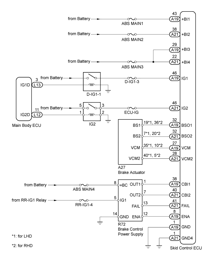
WIRING DIAGRAM
INSPECTION PROCEDURE
Note
When replacing the skid control ECU, perform the following operations:
-
Initialization of linear solenoid valve and calibration Click here
-
Yaw rate and acceleration sensor zero point calibration Click here
PROCEDURE
-
INSPECT BATTERY
-
Check the battery voltage.
Standard voltage 11 to 14 V
NG 
RECHARGE OR REPLACE BATTERY Click here
OK 
-
-
CHECK DTC
-
Clear the DTCs Click here.
-
Turn the power switch OFF.
-
Turn the power switch ON (IG).
-
Check that the DTCs (electronically controlled brake system and hybrid control system) are recorded Click here.
Result Result Proceed to DTCs (C1311/11, C1312/12, C1313/13, C1314/14 and hybrid control system malfunction) are not output A Hybrid control system DTC is output B DTCs (C1311/11, C1312/12, C1313/13 and C1314/14) are output C
B
GO TO HYBRID CONTROL SYSTEM (HOW TO PROCEED WITH TROUBLESHOOTING) Click here
C
REPAIR CIRCUIT INDICATED BY OUTPUT CODE Click here
A
-
-
CHECK HARNESS AND CONNECTOR (IG1, IG2, +BI1, +BI2, +BI3, +BI4)
-
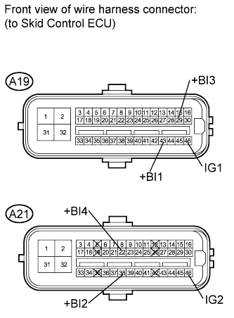
Disconnect the A19 and A21 ECU connectors.
-
Measure the voltage according to the value(s) in the table below.
Standard voltage Tester Connection Switch Condition Specified Condition A19-46 (IG1) - Body ground Power switch ON (IG) 11 to 14 V Power switch OFF Below 1 V A21-46 (IG2) - Body ground Power switch ON (IG) 11 to 14 V Power switch OFF Below 1 V A19-43 (+BI1) - Body ground Always 11 to 14 V A21-38 (+BI2) - Body ground Always 11 to 14 V A19-29 (+BI3) - Body ground Always 11 to 14 V A21-22 (+BI4) - Body ground Always 11 to 14 V
NG
REPAIR OR REPLACE HARNESS OR CONNECTOR
OK
-
-
CHECK HARNESS AND CONNECTOR (GND CIRCUIT)
-
Disconnect the A19 and A21 ECU connectors.
-
Measure the resistance according to the value(s) in the table below.
Standard resistance Tester Connection Condition Specified Condition A19-1 (GND) - Body ground Always Below 1 Ω A21-1 (GND4) - Body ground Always Below 1 Ω
NG
REPAIR OR REPLACE HARNESS OR CONNECTOR
OK
-
-
RECONFIRM DTC
-
Clear the DTC Click here.
-
Turn the power switch ON (READY).
-
After 2 minutes or more have elapsed, drive the vehicle 5 km/h (3 mph) or more for 20 seconds.
-
Check if the same DTCs are recorded Click here.
Result Result Proceed to DTCs (C1241/41 and C1242/42) are not output A DTCs (C1241/41 and C1242/42) are output for LHD B for RHD C Tech Tips
If troubleshooting has been carried out according to the "PROBLEM SYMPTOMS TABLE", refer back to the table and proceed to the next step Click here.
B
REPLACE SKID CONTROL ECU Click here
C
REPLACE SKID CONTROL ECU Click here
A 
USE SIMULATION METHOD TO CHECK Click here
-