ELECTRONICALLY CONTROLLED BRAKE SYSTEM, Diagnostic DTC:C1231/31

| DTC Code | DTC Name |
|---|---|
| C1231/31 | Steering Angle Sensor Circuit Malfunction |
DESCRIPTION
The steering angle sensor signal is sent to the skid control ECU via the CAN communication system. When there is a malfunction in the CAN communication system, it will be detected by the diagnosis function.
| DTC Code | Information Code | DTC Detection Condition | Trouble Area |
|---|---|---|---|
| C1231/31 | 341 | A steering angle sensor malfunction signal other than the sensor malfunction signal (STS1) or +B open malfunction signal (STS2), which are received as part of the steering angle sensor data, indicates the presence of a malfunction (a "stuck malfunction" is present). |
|
| ↑ | 342 | The sensor malfunction signal (STS1), which is received as part of the steering angle sensor data, indicates the presence of a malfunction. | Steering angle sensor |
| ↑ | 344 | The +B open malfunction signal (STS2), which is received as part of the steering angle sensor data, indicates the presence of a malfunction. | ↑ |
WIRING DIAGRAM
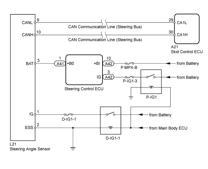
INSPECTION PROCEDURE
Tech Tips
-
If a CAN communication malfunction DTC and a related sensor malfunction DTC are output at the same time, the CAN communication malfunction must be repaired before troubleshooting the sensor malfunction DTC.
-
When the speed sensor or the yaw rate sensor has trouble, DTCs for the steering angle sensor may be output even when the steering angle sensor is normal. When DTCs for the speed sensor or yaw rate sensor are output together with other DTCs for the steering angle sensor, inspect and repair the speed sensor and yaw rate sensor first, and then inspect and repair the steering angle sensor.
-
Start the inspection from "CHECK HARNESS AND CONNECTOR" when using the intelligent tester and start from "CHECK DTC" when not using the intelligent tester.
PROCEDURE
-
CHECK DTC
-
Clear the DTC Click here.
-
Turn the power switch OFF.
-
Turn the power switch ON (READY) again and check that no CAN communication system DTC is output (for LHD: Click here /for RHD: Click here.
-
Drive the vehicle at a speed of 35 km/h (24 mph), turn the steering wheel to the right and left, and check that no speed sensor and yaw rate sensor DTCs are output.
Result Result Proceed to No CAN communication system DTC and speed sensor or yaw rate sensor DTC are output. A CAN communication system DTC is output. for LHD B for RHD C Speed sensor or yaw rate sensor DTC is output. D Tech Tips
-
If there is a malfunction in the speed sensor or the yaw rate sensor, an abnormal value may be output although the steering angle sensor is normal.
-
If the speed sensor and the yaw rate sensor DTCs are output simultaneously, repair the sensors first, and then inspect the steering angle sensor.
-
B 
GO TO CAN COMMUNICATION SYSTEM (HOW TO PROCEED WITH TROUBLESHOOTING) Click here
C
GO TO CAN COMMUNICATION SYSTEM (HOW TO PROCEED WITH TROUBLESHOOTING) Click here
D
CHECK FOR CIRCUIT INDICATED BY OUTPUT CODE Click here
A 
-
-
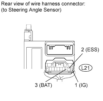
CHECK TERMINAL VOLTAGE AND RESISTANCE (IG, BAT, ESS)
-
Remove the steering wheel and the column cover lower.
-
Disconnect the L21 sensor connector.
-
Measure the voltage according to the value(s) in the table below.
Standard voltage Tester Connection Switch Condition Specified Condition L21-1 (IG) - Body ground Power switch ON (IG) 11 to 14 V L21-3 (BAT) - Body ground Always 11 to 14 V -
Measure the resistance according to the value(s) in the table below.
Standard resistance Tester Connection Switch Condition Specified Condition L21-2 (ESS) - Body ground Always Below 1 Ω Tech Tips
If troubleshooting has been carried out according to the "PROBLEM SYMPTOMS TABLE", refer back to the table and proceed to the next step Click here.
NG
REPAIR OR REPLACE HARNESS OR CONNECTOR
OK 
REPLACE STEERING ANGLE SENSOR Click here
-