ELECTRONICALLY CONTROLLED BRAKE SYSTEM TEST MODE PROCEDURE

-
WARNING LIGHT AND INDICATOR LIGHT BULB CHECK
-
Release the parking brake.
CAUTION:
When releasing the parking brake, set chocks to hold the vehicle for safety.
-
When the power switch is turned ON (IG), check that the VSC OFF indicator light comes on for approximately 3 seconds, and ABS warning, brake warning / red (malfunction), brake warning / yellow (minor malfunction), slip indicator, brake hold standby indicator and brake hold operated indicator lights remain on until the power switch is turned ON (READY).
If the result is not as specified, proceed to troubleshooting for the light circuit below.
Tech Tips
If the skid control ECU stores any DTCs, the ABS warning, brake warning / red (malfunction), brake warning / yellow (minor malfunction) and slip indicator lights will come on. When the brake hold switch is turned on, the brake hold operated indicator light blinks.
Trouble Area See procedure ABS warning light circuit Brake warning light / red (malfunction) circuit Brake warning light / yellow (minor malfunction) circuit Slip indicator light circuit VSC OFF indicator light circuit (light remains on) VSC OFF indicator light circuit (light does not come on) Brake hold standby indicator light circuit Brake hold operated indicator light circuit
-
-
SENSOR SIGNAL CHECK BY TEST MODE (SIGNAL CHECK) (WHEN USING INTELLIGENT TESTER)
Tech Tips
-
After replacing the skid control ECU and/or yaw rate sensor, perform zero point calibration of the yaw rate and acceleration sensor.
-
If the power switch is turned from ON (IG) to ON (ACC) or OFF during Test Mode (signal check), DTCs of the signal check function will be erased.
-
During Test Mode (signal check), the skid control ECU records all DTCs of the signal check function. By performing the Test Mode (signal check), the codes are erased if normality is confirmed. The remaining codes are the codes where an abnormality was found.
-
Procedure for Test Mode.
-
Turn the power switch OFF.
-
Connect the intelligent tester to the DLC3.
-
Check that the steering wheel is centered and move the shift lever to the P position.
-
Turn the power switch ON (IG).
-
Set the intelligent tester to Test Mode (select "Signal Check").
Tech Tips
Refer to the intelligent tester operator's manual for further details.
-
Check that the ABS warning light, slip indicator light and brake warning light / yellow (minor malfunction) blink.
Tech Tips
If the ABS warning light, slip indicator light and brake warning light / yellow (minor malfunction) do not blink, inspect the TS and CG terminal circuit, ABS warning light circuit, slip indictor light circuit and/or brake warning light / yellow (minor malfunction) circuit.
-
Check the following sensors as described below.
-
Acceleration sensor
-
Master cylinder pressure sensor
-
Speed sensor
-
Yaw rate sensor
Tech Tips
Make sure that the ABS warning light is blinking in Test Mode before performing the check.
-
-
-
-
ACCELERATION SENSOR CHECK (WHEN USING INTELLIGENT TESTER)
-
Keep the vehicle stationary on a level surface for 1 second or more.
Tech Tips
The acceleration sensor check can be performed with the following master cylinder pressure sensor check.
-
-
MASTER CYLINDER PRESSURE SENSOR CHECK (WHEN USING INTELLIGENT TESTER)
-
Leave the vehicle in a stationary condition and release the brake pedal for 1 second or more, and quickly depress the brake pedal continuously with a force of 98 N (10 kgf, 22.0 lbf) or more for 1 second.
-
Check that the ABS warning light stays on for 3 seconds.
Tech Tips
-
Ensure that the ABS warning light comes on.
-
While the ABS warning light stays on, continue to depress the brake pedal with a force of 98 N (10 kgf, 22.0 lbf) or more.
-
The ABS warning light comes on for 3 seconds every time brake pedal operation above is performed.
-
-
-
SPEED SENSOR CHECK (WHEN USING INTELLIGENT TESTER)
-
Check the forward signal.
-
Drive the vehicle straight ahead.
Drive the vehicle at a speed of 45 km/h (28 mph) or more for several seconds.
Tech Tips
The signal check may not be completed if the vehicle has its wheels spun.
-
-
Check the backward signal.
-
Drive the vehicle in reverse for more than 1 second at a speed of 3 km/h (2 mph) or more and check that the ABS warning light goes off.
Tech Tips
Drive the vehicle in reverse and check the speed sensor signal. The signal check cannot be completed if the vehicle speed is 45 km/h (28 mph) or more.
-
-
Stop the vehicle.
Note
-
Before performing the speed sensor signal check, complete the acceleration sensor and master cylinder pressure sensor checks.
-
The speed sensor signal check may not be completed if the speed sensor signal check is started while turning the steering wheel or spinning the wheels.
-
If the signal check has not been completed, the ABS warning light blinks while driving and the ABS system does not operate.
Tech Tips
When the signal check has been completed, the ABS warning light goes off while driving, and blinks in the Test Mode pattern while the vehicle is stationary.
-
-
-
YAW RATE SENSOR CHECK (WHEN USING INTELLIGENT TESTER)
-
Perform the check after checking that the slip indicator light and brake warning light / yellow (minor malfunction) blink.
-
Check the zero point voltage of the yaw rate sensor.
-
Keep the vehicle stationary on a level surface for 1 second or more.
Tech Tips
When changing to test mode, if a part or wire harness is malfunctioning, the ABS warning light and brake warning light / yellow (minor malfunction) remain illuminated.
-
-
Check the output of the yaw rate sensor and the direction of the steering angle sensor.
-
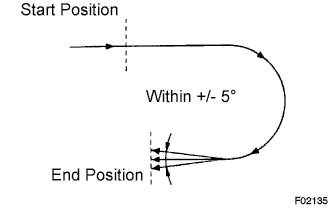
Move the shift lever from the P to the D position, drive the vehicle and turn the steering wheel either to the left or right 90° or more until the vehicle makes a 180° turn.
Tech Tips
-
At the end of the 180° turn, the direction of the vehicle should be within 175 to 185° of its start position.
-
Do not spin the wheels.
-
Do not turn the power switch OFF while turning.
-
Do not move the shift lever to the P position while turning, but changing the vehicle speed, stopping, or driving in reverse is possible.
-
-
Stop the vehicle and move the shift lever to the P position. Check that the skid control buzzer sounds for 3 seconds.
If the skid control buzzer sounds, the signal check is completed normally.
If the skid control buzzer does not sound, check the skid control buzzer circuit, then perform the signal check again. If the skid control buzzer still does not sound, there may be a malfunction in the yaw rate sensor, so check the DTC.
-
-
-
YAW RATE SENSOR DISCRIMINATION
-
Enter test mode and wait for 1 second or more.
Tech Tips
-
This check cannot be performed when the yaw rate sensor has a communication malfunction.
-
The yaw rate sensor must be normal and must not have a communication malfunction. If so, and if the procedure above is performed, the check is complete.
Note
If the yaw rate sensor has a discrimination malfunction, perform the yaw rate sensor and G sensor zero point calibration.
-
-
-
VSC OFF SWITCH CHECK (WHEN USING INTELLIGENT TESTER)
-
Press the VSC OFF switch for a short amount of time.
-
Check that the VSC OFF indicator light comes on.
-
Press the VSC OFF switch again for a short amount of time.
-
Check that the VSC OFF indicator light turns off.
-
-
BRAKE HOLD SWITCH CHECK (WHEN USING INTELLIGENT TESTER)
Tech Tips
Perform the check with the system in a normal condition.
-
Make sure the following conditions are met:
-
The driver side door is closed.
-
The driver side seat belt is fastened.
-
The engine hood is closed.
-
The luggage compartment door is closed.
-
-
Press the brake hold switch.
-
Check that the brake hold standby indicator light is illuminated.
-
Press the brake hold switch again.
-
Check that the brake hold standby indicator light turns off.
-
-
END OF SENSOR CHECK (WHEN USING INTELLIGENT TESTER)
-
If the sensor check is completed, the ABS warning light blinks (Test Mode) when the vehicle stops, and the ABS warning light goes off when the vehicle is driving.
Note
-
When the yaw rate sensor, acceleration sensor, speed sensor and master cylinder pressure sensor checks are finished, all the sensor checks are completed.
-
If all sensor checks are not completed, the ABS warning light blinks even while the vehicle is driving and the ABS does not operate.
-
-
-
READ DTC OF SIGNAL CHECK FUNCTION (WHEN USING INTELLIGENT TESTER)
-
Read the DTC(s) by following the tester prompt.
Note
-
If only DTCs are displayed, repair the malfunction area and clear the DTCs.
-
If only Test Mode codes (DTC of signal check function) are displayed, repair the malfunction area, clear the Test Mode codes and perform the Test Mode inspection.
-
If DTCs and Test Mode codes (DTCs of the signal check function) are displayed, repair the malfunction, clear the DTCs and Test Mode codes and perform the Test Mode inspection.
Tech Tips
-
If more than 1 malfunction is detected at the same time, the lowest numbered code will be displayed first.
-
See the list of DTCs Click here.
-
-
-
DTC OF TEST MODE FUNCTION (SIGNAL CHECK) (WHEN USING INTELLIGENT TESTER)
ABS sensor: Code No. Diagnosis Trouble Area C1271/71 Low output signal of front speed sensor RH
-
Front speed sensor RH
-
Sensor installation
-
Speed sensor rotor
C1272/72 Low output signal of front speed sensor LH
-
Front speed sensor LH
-
Sensor installation
-
Speed sensor rotor
C1273/73 Low output signal of rear speed sensor RH
-
Rear speed sensor RH
-
Sensor installation
-
Speed sensor rotor
C1274/74 Low output signal of rear speed sensor LH
-
Rear speed sensor LH
-
Sensor installation
-
Speed sensor rotor
C1275/75 Abnormal change in output signal of front speed sensor RH
-
Front speed sensor RH
-
Speed sensor circuit
-
Sensor installation
C1276/76 Abnormal change in output signal of front speed sensor LH
-
Front speed sensor LH
-
Speed sensor circuit
-
Sensor installation
C1277/77 Abnormal change in output signal of rear speed sensor RH
-
Rear speed sensor RH
-
Speed sensor circuit
-
Sensor installation
C1278/78 Abnormal change in output signal of rear speed sensor LH
-
Rear speed sensor LH
-
Speed sensor circuit
-
Sensor installation
C1279/79 Deceleration sensor output voltage malfunction
-
Yaw rate sensor
-
Sensor installation
C1281/81 Master cylinder pressure sensor output malfunction
-
Master cylinder pressure sensor
-
Master cylinder pressure sensor circuit
-
Stop light switch circuit
-
Brake actuator
VSC sensor: Code No. Diagnosis Trouble Area C1473/71 Yaw rate sensor output malfunction
-
Yaw rate sensor
-
Sensor installation
Electronically controlled brake system sensor: Code No. Diagnosis Trouble Area C1346/71 Stroke sensor zero point learning malfunction Brake pedal stroke sensor Tech Tips
-
The codes in this table are output only in Test Mode (signal check).
-
If the test mode DTC C1346/71 is not cleared, adjust the brake pedal stroke sensor Click here.
-
-
SENSOR SIGNAL CHECK BY TEST MODE (SIGNAL CHECK) (WHEN USING SST CHECK WIRE)
Tech Tips
-
After replacing the skid control ECU and/or yaw rate sensor, perform zero point calibration of the yaw rate and acceleration sensor.
-
If the power switch is turned from ON (IG) to ON (ACC) or OFF during Test Mode (signal check), DTCs of the signal check function will be erased.
-
During Test Mode (signal check), the skid control ECU records all DTCs of the signal check function. By performing the Test Mode (signal check), the codes are erased if normality is confirmed. The remaining codes are the codes where an abnormality was found.
-
Procedure for Test Mode.
-
Turn the power switch OFF.
-
Check that the steering wheel is in the centered position and move the shift lever to the P position.
-
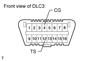
Using SST, connect terminals 12 (TS) and 4 (CG) of the DLC3.
- SST
- 09843-18040
-
Turn the power switch ON (IG).
-
Check that the ABS warning light, slip indicator light and brake warning light / yellow (minor malfunction) blink.
Tech Tips
If the ABS warning light, slip indicator light and brake warning light / yellow (minor malfunction) do not blink, inspect the TS and CG terminal circuit, ABS warning light circuit, slip indicator light circuit and/or brake warning light / yellow (minor malfunction) circuit.
-
Check the following sensors as described below.
-
Acceleration sensor
-
Master cylinder pressure sensor
-
Speed sensor
-
Yaw rate sensor
Tech Tips
Make sure that the ABS warning light is blinking in Test Mode before performing the check.
-
-
-
-
ACCELERATION SENSOR CHECK (WHEN USING SST CHECK WIRE)
-
Keep the vehicle stationary on a level surface for 1 second or more.
Tech Tips
The acceleration sensor check can be performed with the following master cylinder pressure sensor check.
-
-
MASTER CYLINDER PRESSURE SENSOR CHECK (WHEN USING SST CHECK WIRE)
-
Leave the vehicle in a stationary condition and release the brake pedal for 1 second or more, and quickly depress the brake pedal continuously with a force of 98 N (10 kgf, 22.0 lbf) or more for 1 second.
-
Check that the ABS warning light stays on for 3 seconds.
Tech Tips
-
Ensure that the ABS warning light comes on.
-
While the ABS warning light stays on, continue to depress the brake pedal with a force of 98 N (10 kgf, 22.0 lbf) or more.
-
The ABS warning light comes on for 3 seconds every time the brake pedal operation above is performed.
-
-
-
SPEED SENSOR CHECK (WHEN USING SST CHECK WIRE)
-
Check the forward signal.
-
Drive the vehicle straight ahead.
Drive the vehicle at a speed of 45 km/h (28 mph) or more for several seconds.
Tech Tips
The signal check may not be completed if the vehicle has its wheels spun.
-
-
Check the backward signal.
-
Drive the vehicle in reverse for more than 1 second at a speed of 3 km/h (2 mph) or more and check that the ABS warning light goes off.
Tech Tips
Drive the vehicle in reverse and check the speed sensor signal. The signal check cannot be completed if the vehicle speed is 45 km/h (28 mph) or more.
-
-
Stop the vehicle.
Note
-
Before performing the speed sensor signal check, complete the acceleration sensor and master cylinder pressure sensor checks.
-
The speed sensor signal check may not be completed if the speed sensor signal check is started while turning the steering wheel or spinning the wheels.
-
If the signal check has not been completed, the ABS warning light blinks while driving and the ABS system does not operate.
Tech Tips
When the signal check has been completed, the ABS warning light goes off while driving, and blinks in the Test Mode pattern while the vehicle is stationary.
-
-
-
YAW RATE SENSOR CHECK (WHEN USING SST CHECK WIRE)
-
Perform the check after checking that the slip indicator light and brake warning light / yellow (minor malfunction) blink.
-
Check the zero point voltage of the yaw rate sensor.
-
Keep the vehicle stationary on a level surface for 1 second or more.
Tech Tips
When changing to test mode, if a part or wire harness is malfunctioning, the ABS warning light and brake warning light / yellow (minor malfunction) remain illuminated.
-
-
Check the output of the yaw rate sensor and the direction of the steering angle sensor.
-
Move the shift lever from the P to the D position, drive the vehicle and turn the steering wheel either to the left or right 90° or more until the vehicle makes a 180° turn.
Tech Tips
-
At the end of the 180° turn, the direction of the vehicle should be within 175 to 185° of its start position.
-
Do not spin the wheels.
-
Do not turn the power switch OFF while turning.
-
Do not move the shift lever to the P position while turning, but changing the vehicle speed, stopping, or driving in reverse is possible.
-
-
Stop the vehicle and move the shift lever to the P position. Check that the skid control buzzer sounds for 3 seconds.
If the skid control buzzer sounds, the signal check is completed normally.
If the skid control buzzer does not sound, check the skid control buzzer circuit, then perform the signal check again. If the skid control buzzer still does not sound, there may be a malfunction in the yaw rate sensor, so check the DTC.
-
-
-
VSC OFF SWITCH CHECK (WHEN USING SST CHECK WIRE)
-
Press the VSC OFF switch for a short amount of time.
-
Check that the VSC OFF indicator light comes on.
-
Press the VSC OFF switch again for a short amount of time.
-
Check that the VSC OFF indicator light turns off.
-
-
BRAKE HOLD SWITCH CHECK (WHEN USING SST CHECK WIRE)
Tech Tips
Perform the check with the system in a normal condition.
-
Make sure the following conditions are met:
-
The driver side door is closed.
-
The driver side seat belt is fastened.
-
The engine hood is closed.
-
The luggage compartment door is closed.
-
-
Press the brake hold switch.
-
Check that the brake hold standby indicator light is illuminated.
-
Press the brake hold switch again.
-
Check that the brake hold standby indicator light turns off.
-
-
END OF SENSOR CHECK (WHEN USING SST CHECK WIRE)
-
If the sensor check is completed, the ABS warning light blinks (Test Mode) when the vehicle stops and the ABS warning light goes off when the vehicle is driving.
Note
-
When the yaw rate sensor, acceleration sensor, speed sensor and master cylinder pressure sensor checks are completed, the sensor checks are completed.
-
If all sensor checks are not completed, the ABS warning light blinks even while the vehicle is driving and the ABS does not operate.
-
-
-
READ DTC OF SIGNAL CHECK FUNCTION (WHEN USING SST CHECK WIRE)
-
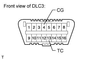
Using SST, connect terminals 13 (TC) and 4 (CG) of the DLC3.
- SST
- 09843-18040
-
Count the number of blinks of the ABS warning light, brake warning light / yellow (minor malfunction), slip indicator light and brake hold standby indicator light.
Note
-
If only the DTCs are displayed, repair the malfunction area and clear the DTCs.
-
If only Test Mode codes (DTC of signal check function) are displayed, repair the malfunction area, clear the Test Mode codes and perform the Test Mode inspection.
-
If DTCs and Test Mode codes (DTCs of the signal check function) are displayed, repair the malfunction, clear the DTCs and Test Mode codes and perform the Test Mode inspection.
Tech Tips
-
When the system is normal, the relevant light turns on for 0.25 seconds and off for 0.25 seconds and repeats this pattern.
-
When only 1 DTC is stored, the relevant light outputs the same code after an interval of 4 seconds. Example: When DTC 71 is stored, the light blinks 7 times, turns off for 1.5 seconds, blinks once, turns off for 4 seconds, and then repeats this output pattern.
-
When 2 or more DTCs are stored, the relevant light outputs the codes with an interval of 2.5 seconds between each different code, and the output of all codes repeats after an interval of 4 seconds.
-
If more than 1 malfunction is detected at the same time, the lowest numbered code will be displayed first.
-
See the list of DTCs Click here.
-
-
Turn the power switch OFF. Then disconnect SST from terminals 12 (TS), 4 (CG), and 13 (TC) of the DLC3.
-
Turn the power switch ON (IG).
Tech Tips
If the power switch is not turned ON (IG) after SST is removed from the DLC3, the previous Test Mode will continue.
-
-
DTC OF TEST MODE FUNCTION (SIGNAL CHECK) (WHEN USING SST CHECK WIRE)
ABS sensor: Code No. Diagnosis Trouble Area C1271/71 Low output signal of front speed sensor RH
-
Front speed sensor RH
-
Sensor installation
-
Speed sensor rotor
C1272/72 Low output signal of front speed sensor LH
-
Front speed sensor LH
-
Sensor installation
-
Speed sensor rotor
C1273/73 Low output signal of rear speed sensor RH
-
Rear speed sensor RH
-
Sensor installation
-
Speed sensor rotor
C1274/74 Low output signal of rear speed sensor LH
-
Rear speed sensor LH
-
Sensor installation
-
Speed sensor rotor
C1275/75 Abnormal change in output signal of front speed sensor RH
-
Front speed sensor RH
-
Speed sensor circuit
-
Sensor installation
C1276/76 Abnormal change in output signal of front speed sensor LH
-
Front speed sensor LH
-
Speed sensor circuit
-
Sensor installation
C1277/77 Abnormal change in output signal of rear speed sensor RH
-
Rear speed sensor RH
-
Speed sensor circuit
-
Sensor installation
C1278/78 Abnormal change in output signal of rear speed sensor LH
-
Rear speed sensor LH
-
Speed sensor circuit
-
Sensor installation
C1279/79 Deceleration sensor output voltage malfunction
-
Yaw rate sensor
-
Sensor installation
C1281/81 Master cylinder pressure sensor output malfunction
-
Master cylinder pressure sensor
-
Master cylinder pressure sensor circuit
-
Stop light switch circuit
-
Brake actuator
VSC sensor: Code No. Diagnosis Trouble Area C1473/71 Yaw rate sensor output malfunction
-
Yaw rate sensor
-
Sensor installation
Electronically controlled brake system sensor: Code No. Diagnosis Trouble Area C1346/71 Stroke sensor zero point learning malfunction Brake pedal stroke sensor Tech Tips
-
The codes in this table are output only in Test Mode (signal check).
-
If the test mode DTC C1346/71 is not cleared, adjust the brake pedal stroke sensor Click here.
-