ELECTRONICALLY CONTROLLED BRAKE SYSTEM PRECAUTION

-
TROUBLESHOOTING PRECAUTIONS
-
When there is a malfunction with terminal contact points or a problem with part installation, removal and installation of the suspected problem parts may return the system to the normal condition either completely or temporarily.
-
In order to determine the malfunctioning area, be sure to check the conditions at the time the malfunction occurred, such as DTC output and the freeze frame data, and record it before disconnecting each connector or removing and installing parts.
-
Since this system may be influenced by malfunctions in systems other than the brake control system, be sure to also check for DTCs in other systems.
-
-
HANDLING PRECAUTIONS
-
Do not remove or install the electronically controlled brake system parts such as the steering angle sensor, yaw rate and acceleration sensor or brake pedal stroke sensor except when required, as they need to be adjusted correctly after removal and installation.
-
When replacing the skid control ECU assembly, always install a new one.
Note
Do not use the skid control ECU assembly from another vehicle (vehicle on display, etc.).
-
Be sure to complete preparation before work and confirmation after work by following the directions in the repair manual when working on the electronically controlled brake system.
-
Be sure to remove and install the skid control ECU, brake actuator, brake accumulator pump, each sensor, etc. with the power switch OFF unless otherwise specified in the inspection procedure.
-
While the battery is connected, even if the power switch is OFF, the brake control system activates when the brake pedal is depressed or the door courtesy switch turns on. Therefore during servicing of the brake system components, do not operate the brake pedal and open/close the doors while the battery is connected.
-
The removal and installation of the brake actuator, brake accumulator pump, brake master cylinder or brake stroke simulator cylinder as well as other procedures can cause the fluid level to drop below the fluid reservoir port. If this happens when performing such work, be sure to remove the 2 connectors of the brake accumulator pump before the bleeding of the air in the pipeline is completed.
Tech Tips
-
When the pump motor is operated with the air in the brake actuator hose, bleeding of the air becomes difficult due to the air in the actuator.
-
The skid control ECU may operate the brake stroke simulator cylinder and drive the pump motor even when the power switch is turned OFF.
-
Even with the power switch turned OFF, the skid control ECU can be operated for 2 minutes after the brake operation is finished.
-
-
When removing and installing the skid control ECU, brake actuator, brake accumulator pump and each sensor, be sure to check that the normal display is output in the Test Mode inspection and in DTC output inspection after installing all the parts.
-
-
DTC PRECAUTION
-
Warnings for some DTCs cannot be cleared only by repairing the malfunctioning parts. If the warning is displayed after repair work, the DTC should be cleared after turning the power switch OFF.
Note
If a part is still malfunctioning even after the DTC is cleared, the DTC will be stored again.
-
-
CHASSIS DYNAMOMETER PRECAUTION
-
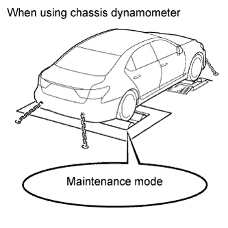
Enter the "MAINTENANCE MODE" to disable TR(A)C and VSC control when using chassis dynamometer.
CAUTION:
-
Enter the "MAINTENANCE MODE" with the intelligent tester, when using chassis dynamometer Click here.
-
If the vehicle is tested in normal mode on the drum tester, the traction control and VSC system may cause the vehicle to jump out from the drum tester.
When testing with a 2-wheel drum tester such as a speedometer tester, a combination tester for the speedometer and brake, a chassis dynamometer, or when jacking up the rear wheels and turning the wheels, enter the "MAINTENANCE MODE" with the intelligent tester and change to traction control off mode and VSC system off mode.
Note
-
Check that the multi-information display shows the TR(A)C OFF display.
-
Check that the VSC OFF indicator light illuminates on the combination meter.
-
For safety, secure the vehicle with restraint chains while using a drum tester.
-
When performing procedures related to VSC OFF switch operation, make sure the mode is VSC OFF mode.
-
-
-
CAN COMMUNICATION SYSTEM PRECAUTION
-
The CAN communication system is used for the data communication between the skid control ECU, the steering angle sensor, the yaw rate and acceleration sensor and other ECUs. If there is trouble with the CAN communication line, corresponding DTCs in the communication line will be output.
-
If the DTC in the CAN communication line is output, repair the malfunction in the communication line and troubleshoot the electronically controlled brake system while data communication is normal.
-
Since the CAN communication line has a specific length and route, it cannot be repaired temporarily with a bypass wire, etc.
-
-
PRECAUTIONS WHEN USING INTELLIGENT TESTER
-
When using the intelligent tester with the power switch OFF to troubleshoot: Connect the intelligent tester to the vehicle, and turn a courtesy light switch on and off at 1.5 second intervals until communication between the tester and vehicle begins.
-
After all DTCs are cleared, check if the trouble occurs again 6 seconds after the power switch is turned ON (IG).
-