TIRE PRESSURE WARNING SYSTEM TC and CG Terminal Circuit
DESCRIPTION
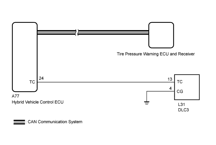
DTC output mode is set by connecting terminals 13 (TC) and 4 (CG) of the DLC3. The DTCs are indicated by the tire pressure warning light blinking pattern.
WIRING DIAGRAM
Tech Tips
If the tire pressure warning light blinks continuously, a ground short in the wiring of terminal TC of the DLC3 or an internal ground short in each ECU is suspected.
INSPECTION PROCEDURE
PROCEDURE
-
CHECK CAN COMMUNICATION LINE
-
Turn the power switch off.
-
Connect the GTS to the DLC3.
-
Turn the power switch on (IG) and turn the GTS on.
-
Enter the following menus: "CAN Bus Check" from the "System Select" screen.
-
Check the CAN communication system (for LHD: Click here, for RHD: Click here.
OK The CAN communication system is normal. Result Result Proceed to OK A NG (for LHD) B NG (for RHD) C
B 
GO TO CAN COMMUNICATION SYSTEM Click here
C
GO TO CAN COMMUNICATION SYSTEM Click here
A 
-
-
CHECK HARNESS AND CONNECTOR (DLC3 - HYBRID VEHICLE CONTROL ECU)
-
Disconnect the hybrid vehicle control ECU A77 connector.
-
Measure the resistance according to the value(s) in the table below.
Standard Resistance Tester Connection Condition Specified Condition L31-13 (TC) - A77-24 (TC) Always Below 1 Ω L31-13 (TC) or A77-24 (TC) - Body ground Always 10 kΩ or higher L31-4 (CG) - Body ground Always Below 1 Ω
NG
REPAIR OR REPLACE HARNESS OR CONNECTOR
OK
-
-
INSPECT DLC3 (TC VOLTAGE)
-
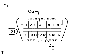
Text in Illustration *a Front view of DLC3 Connect the hybrid vehicle control ECU A77 connector.
-
Measure the voltage according to the value(s) in the table below.
Standard Voltage Tester Connection Switch Condition Specified Condition L31-13 (TC) - L31-4 (CG) Power switch on (IG) 11 to 14 V
NG
REPLACE HYBRID VEHICLE CONTROL ECU Click here
OK 
PROCEED TO NEXT SUSPECTED AREA SHOWN IN PROBLEM SYMPTOMS TABLE Click here
-