REAR ACTIVE STABILIZER CONTROL ACTUATOR INSTALLATION

Tech Tips
A bolt without a torque specification is shown in the standard bolt chart Click here.
-
INSTALL REAR STABILIZER BUSH
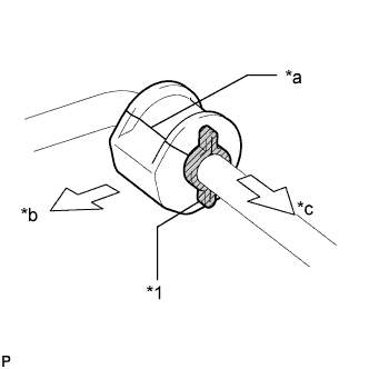
Text in Illustration *1 Bush Stopper *a Seam *b Rear of Vehicle *c Inside of Vehicle
-
Install the 2 stabilizer bar bushes outside of the bush stoppers on the rear active stabilizer control actuator as shown in the illustration.
Note
Make sure to face the stabilizer bar bush's seam to the upper rear of the vehicle.
-
-
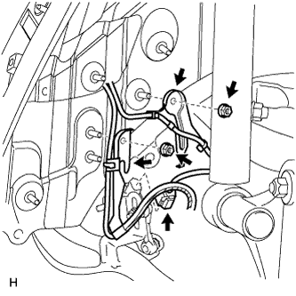
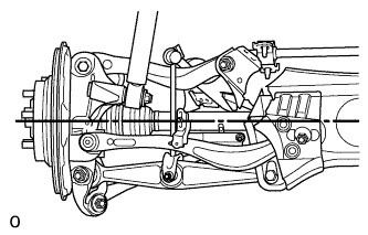
INSTALL REAR ACTIVE STABILIZER CONTROL ACTUATOR ASSEMBLY
-
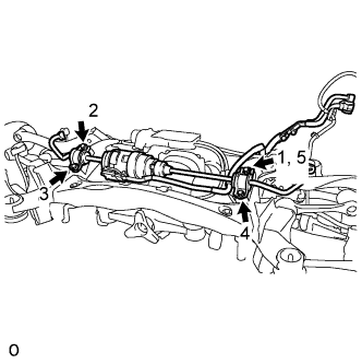
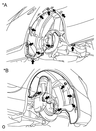
First, temporarily install bolt 1. Then install bolts 2, 3 and 4. Then tighten bolt 5.
- Torque:
- 51 N*m { 520 kgf*cm, 38 ft.*lbf }
-
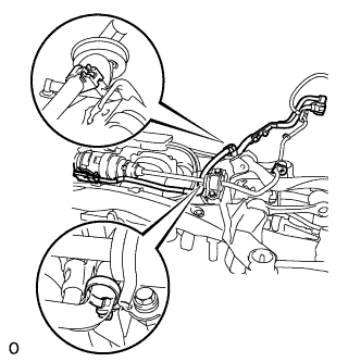
Attach the 2 claws, and install the wire harness to the suspension member.
-
-
INSTALL REAR STABILIZER LINK ASSEMBLY LH
-
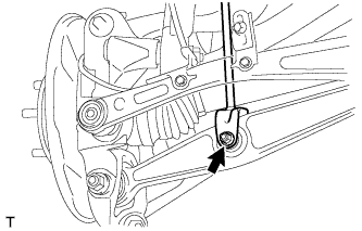
Install the stabilizer link with the nut and bolt.
- Torque:
- 26 N*m { 265 kgf*cm, 19 ft.*lbf }
-
Install the stabilizer link with the nut.
- Torque:
- 89 N*m { 908 kgf*cm, 66 ft.*lbf }
-
-
INSTALL REAR STABILIZER LINK ASSEMBLY RH
Tech Tips
Use the same procedures described for the LH side.
-
INSTALL REAR SUSPENSION MEMBER SUB-ASSEMBLY
-
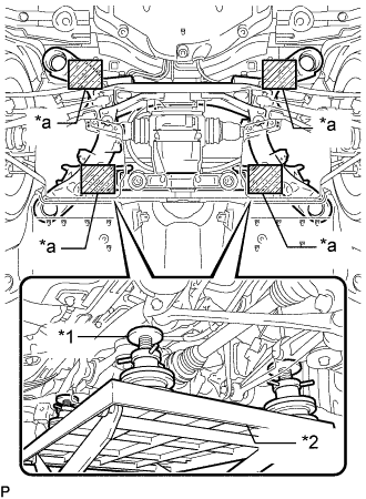
Text in Illustration *1 Attachment *2 Engine Lifter *a Attachment placement location Support the rear suspension member sub-assembly with an engine lifter using 4 attachments or equivalent tools.
Note
-
Make sure to secure the rear suspension member sub-assembly to prevent it from dropping.
-
Use the attachments to keep the rear suspension member sub-assembly level.
-
The rear suspension member sub-assembly is a heavy component. Make sure that it is supported securely.
-
-
Raise the rear suspension member sub-assembly until there is no clearance between the rear suspension member sub-assembly and the body.
Note
When raising the rear suspension member subassembly, be careful not to damage the vehicle body or other components installed on the vehicle.
-
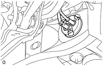
Attach the 3 claws, and install the grommet to the body.
Tech Tips
Install the grommet so that the arrow of the grommet is facing the top of the vehicle.
-
Install the 2 member stoppers with the 4 bolts labeled B, and install the 4 bolts labeled A.
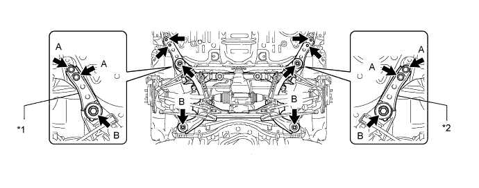
Text in Illustration *1 Suspension Member Stopper Lower RH *2 Suspension Member Stopper Lower LH - Torque:
- for bolt A
- 19 N*m { 194 kgf*cm, 14 ft.*lbf }
- for bolt B
- 127 N*m { 1295 kgf*cm, 94 ft.*lbf }
-
-
TEMPORARILY INSTALL PNEUMATIC CYLINDER WITH REAR SHOCK ABSORBER ASSEMBLY LH
-
Connect the nut on the axle carrier.
- Torque:
- 80 N*m { 816 kgf*cm, 59 ft.*lbf }
-
-
TEMPORARILY INSTALL PNEUMATIC CYLINDER WITH REAR SHOCK ABSORBER ASSEMBLY RH
Tech Tips
Use the same procedures described for the LH side.
-
INSTALL REAR DISC BRAKE CALIPER ASSEMBLY LH
-
Connect the rear disc brake caliper assembly LH with new 2 bolts.
- Torque:
- 86 N*m { 877 kgf*cm, 63 ft.*lbf }
Note
-
Do not twist the flexible hose.
-
Make sure the screw parts are free from foreign matter and are not damaged.
-
Be careful not to overtighten the bolts, as the rear axle carrier is made of aluminum.
-
-
INSTALL REAR DISC BRAKE CALIPER ASSEMBLY RH
Tech Tips
Use the same procedures described for the LH side.
-
INSTALL LOAD SENSING VALVE SENSOR BRACKET
-
Install the bracket to the toe control link with the bolt.
-
-
INSTALL REAR HEIGHT CONTROL SENSOR SUB-ASSEMBLY LH
-
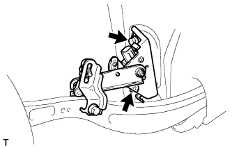
Install the height control sensor with the 2 bolts.
- Torque:
- 14 N*m { 138 kgf*cm, 10 ft.*lbf }
Note
Do not drop the height control sensor. If it is dropped, replace it with a new one.
-
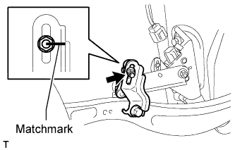
Align the matchmarks on the height control sensor link and bracket.
-
Install the nut to the height control sensor link.
- Torque:
- 5.3 N*m { 54 kgf*cm, 47 in.*lbf }
-
Connect the connector.
-
-
INSTALL REAR HEIGHT CONTROL SENSOR SUB-ASSEMBLY RH
Tech Tips
Use the same procedures described for the LH side.
-
INSTALL SKID CONTROL SENSOR WIRE
-
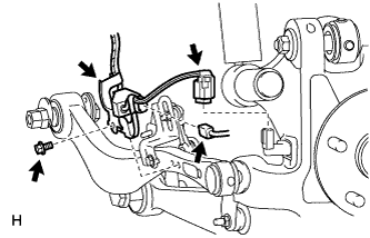
Connect the rear speed sensor connector.
-
Connect the pad wear indicator connector.
-
Install the sensor clamp with the bolt.
- Torque:
- 8.5 N*m { 87 kgf*cm, 75 in.*lbf }
Note
Do not twist the sensor wire when installing the clamps.
-
Install the 2 sensor clamps with the 2 nuts.
-
Connect the rear height control sensor connector.
-
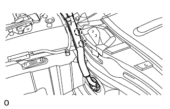
Insert the connector and grommet to the inside of the vehicle through the hole in the wheel house.
-
for RH:
-
Connect the skid control sensor wire connector to the vehicle side connector.
-
-
for LH:
-
Connect the skid control sensor wire connector to the vehicle side connector.
-
-
-
INSTALL REAR WHEEL HOUSE LINER LH
Text in Illustration *1 Front Side *2 Rear Side
-
Install the liner with the 3 screws, 11 nuts, 2 clips to the vehicle side.
-
-
INSTALL PROPELLER SHAFT WITH CENTER BEARING ASSEMBLY
-
INSTALL ELECTRIC PARKING BRAKE ACTUATOR CAP
-
CONNECT WIRE HARNESS CLAMP
-
CONNECT ELECTRIC PARKING BRAKE ACTUATOR CONNECTOR
-
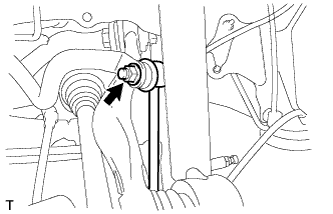
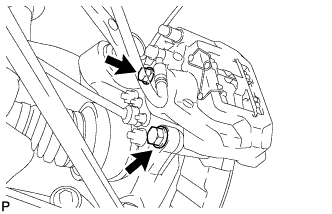
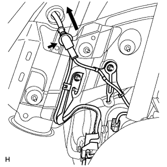
CONNECT REAR ACTIVE STABILIZER CONTROL ACTUATOR CONNECTOR
-
Attach the 2 clamps to install the wire harness to the body.
-
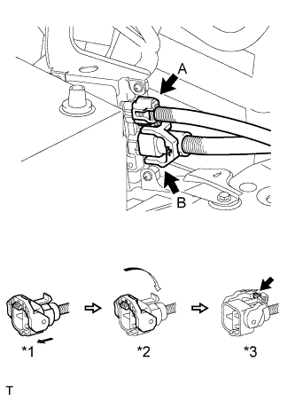
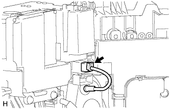
Connect the actuator connector labeled A.
-
Connect the actuator connector labeled B.
-
Connect the actuator connector. (*1)
-
Rotate the lever in the direction of the arrow until a "click" sound is heard. (*2)
-
Lock the lever's lock. (*3)
-
-
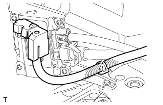
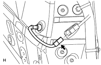
Attach the wire harness clamp to the bracket.
-
-
INSTALL LUGGAGE COMPARTMENT TRIM COVER ASSEMBLY LH
-
STABILIZE SUSPENSION
-
Install the rear tires.
- Torque:
- 140 N*m { 1428 kgf*cm, 103 ft.*lbf }
-
Lower the vehicle and start the engine. Then fill the pneumatic cylinder assembly with rear shock absorber with air.
-
Lower the vehicle and bounce it up and down several times to stabilize the rear suspension.
-
Remove the rear tires.
-
Jack up the axle carrier with a wooden block between the jack and axle carrier. Apply a load to the suspension so that the rear drive shaft assembly is placed in a horizontal position.
-
-
TIGHTEN PNEUMATIC CYLINDER WITH REAR SHOCK ABSORBER ASSEMBLY LH
-
Tighten the nut on the axle carrier.
- Torque:
- 80 N*m { 816 kgf*cm, 59 ft.*lbf }
-
-
TIGHTEN PNEUMATIC CYLINDER WITH REAR SHOCK ABSORBER ASSEMBLY RH
Tech Tips
Use the same procedures described for the LH side.
-
INSTALL REAR WHEEL
- Torque:
- 140 N*m { 1428 kgf*cm, 103 ft.*lbf }
-
CHECK SUSPENSION CONTROL SYSTEM
-
Check the suspension control system Click here.
-
-
INSPECT AND ADJUST REAR WHEEL ALIGNMENT
-
Inspect and adjust the rear wheel alignment Click here.
-
-
CHECK SPEED SENSOR SIGNAL
-
Check the speed sensor signal Click here.
-
-
ADJUST HEADLIGHT ASSEMBLY
-
Adjust the headlight Click here.
-
-
ADJUST OBJECT RECOGNITION CAMERA
-
Adjust the object recognition camera Click here.
-