REAR ACTIVE STABILIZER CONTROL ACTUATOR REMOVAL

-
REMOVE REAR WHEEL
-
REMOVE LUGGAGE COMPARTMENT TRIM COVER ASSEMBLY LH
-
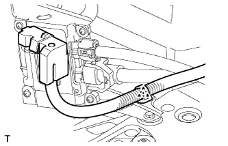
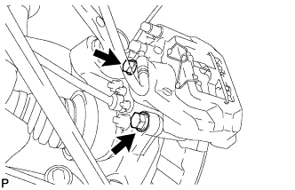
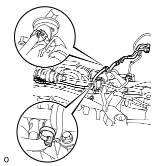
DISCONNECT REAR ACTIVE STABILIZER CONTROL ACTUATOR CONNECTOR
-
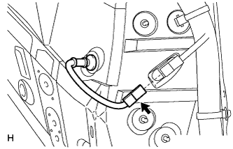
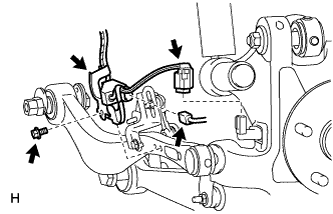
Detach the wire harness clamp.
-
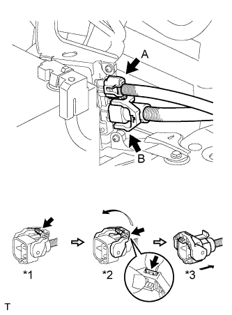
Disconnect the actuator connector labeled A.
-
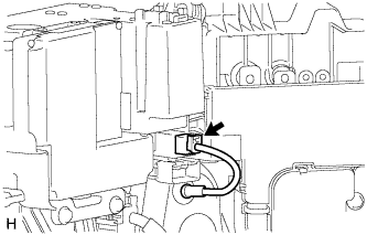
Disconnect the actuator connector labeled B.
-
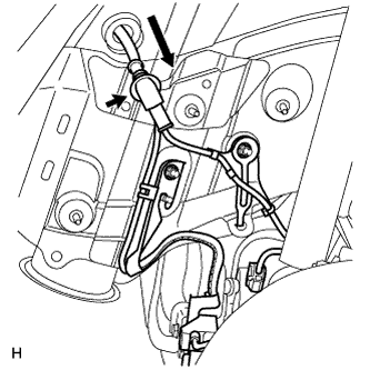
Release the lever's lock. (*1)
-
Press the claw and move the lever in the direction of the arrow in the illustration. (*2)
-
Disconnect the actuator connector. (*3)
Note
When disconnecting the actuator connector, do not apply excessive force to the wire harness.
-
-
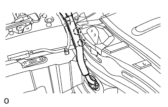
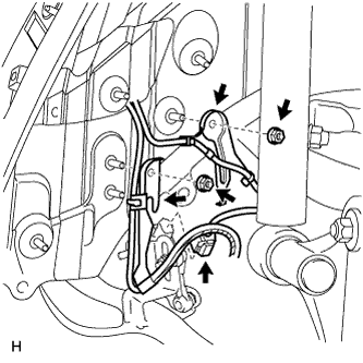
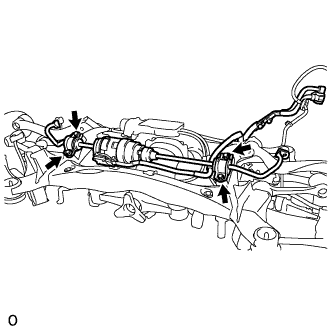
Detach the 2 clamps, and disconnect the actuator wire harness from the body.
-
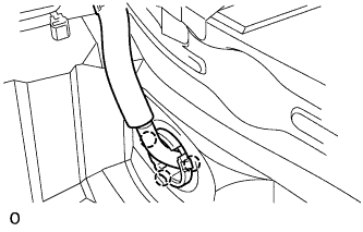
Detach the 3 claws, and disconnect the wire harness grommet from the body.
-
-
DISCONNECT ELECTRIC PARKING BRAKE ACTUATOR CONNECTOR
-
DISCONNECT WIRE HARNESS CLAMP
-
DISCONNECT ELECTRIC PARKING BRAKE ACTUATOR CAP
-
REMOVE PROPELLER SHAFT WITH CENTER BEARING ASSEMBLY
-
REMOVE REAR WHEEL HOUSE LINER LH
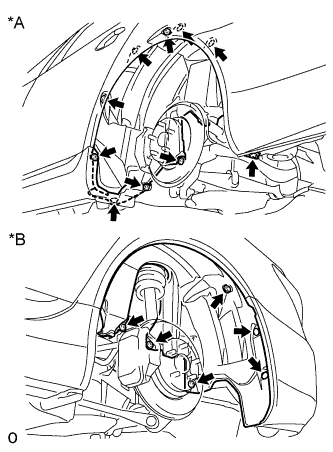
Text in Illustration *A Front Side *B Rear Side
-
Remove the 4 screws, 11 nuts and 2 clips from the liner.
-
-
REMOVE SKID CONTROL SENSOR WIRE
-
for RH:
-
Disconnect the sensor connector from the vehicle side connector.
-
-
for LH:
-
Disconnect the sensor connector from the vehicle side connector.
-
-
Disconnect the grommet of the speed sensor wire from the hole of the wheel house.
-
Disconnect the rear height control sensor connector.
-
Remove the 2 nuts and 2 sensor clamps.
-
Disconnect the pad wear indicator connector.
-
Remove the bolt and sensor clamp.
-
Disconnect the rear speed sensor connector.
Note
-
Be careful not to damage the speed sensor.
-
Prevent foreign matter from adhering to the speed sensor.
-
-
-
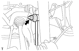
REMOVE REAR HEIGHT CONTROL SENSOR SUB-ASSEMBLY LH
-
Disconnect the connector.
-
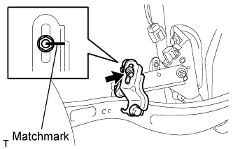
Place matchmarks on the height control sensor link and bracket.
-
Remove the nut and disconnect the height control sensor link from the bracket.
-
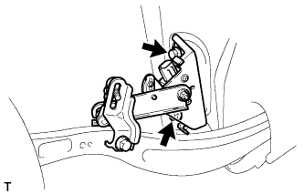
Remove the 2 bolts and height control sensor from the rear suspension member.
Note
Do not drop the height control sensor. If it is dropped, replace it with a new one.
-
-
REMOVE REAR HEIGHT CONTROL SENSOR SUB-ASSEMBLY RH
-
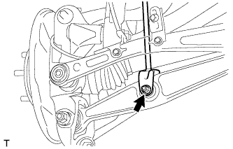
REMOVE LOAD SENSING VALVE SENSOR BRACKET
-
Remove the bolt and bracket from the toe control link.
-
-
REMOVE REAR DISC BRAKE CALIPER ASSEMBLY LH
-
Remove the 2 bolts and disconnect the rear disc brake caliper assembly.
Note
-
Hang the caliper with wire or equivalent.
-
Do not damage the brake hose.
-
-
-
REMOVE REAR DISC BRAKE CALIPER ASSEMBLY RH
Tech Tips
Use the same procedures described for the LH side.
-
REMOVE REAR STABILIZER LINK ASSEMBLY LH
-
Remove the nut and disconnect the stabilizer link from the stabilizer bar.
-
Remove the bolt, nut and stabilizer link from the rear No. 2 suspension arm.
-
-
REMOVE REAR STABILIZER LINK ASSEMBLY RH
Tech Tips
Use the same procedures described for the LH side.
-
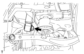
DISCONNECT PNEUMATIC CYLINDER WITH REAR SHOCK ABSORBER ASSEMBLY LH
-
Remove the nut and disconnect the pneumatic cylinder from the axle side.
-
-
DISCONNECT PNEUMATIC CYLINDER WITH REAR SHOCK ABSORBER ASSEMBLY RH
-
REMOVE REAR SUSPENSION MEMBER SUB-ASSEMBLY
-
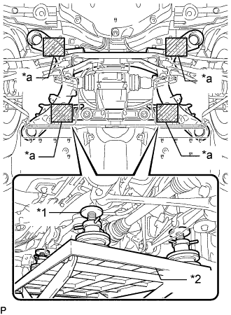
Text in Illustration *1 Attachment *1 Engine Lifter *a Attachment placement location Support the rear suspension member sub-assembly with an engine lifter using 4 attachments or equivalent tools as shown in the illustration.
Note
-
Use the attachments to keep the rear suspension member sub-assembly level.
-
The rear suspension member sub-assembly is a heavy component. Make sure that it is supported securely.
-
-
Remove the 4 bolts labeled A.
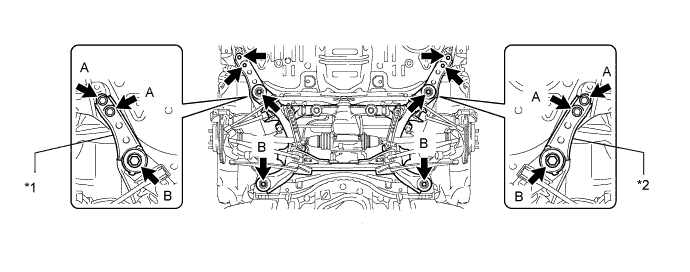
Text in Illustration *1 Suspension Member Stopper Lower RH *2 Suspension Member Stopper Lower LH -
Remove the 4 bolts labeled B and 2 suspension member stoppers.
-
Slowly lower the rear suspension member subassembly.
Note
When lowering the rear suspension member sub-assembly, be careful not to damage the vehicle body or other components installed on the vehicle.
-
-
REMOVE REAR ACTIVE STABILIZER CONTROL ACTUATOR ASSEMBLY
-
Disconnect the 2 claws, and remove the wire harness from the suspension member.
-
Remove the 4 bolts and active stabilizer from the suspension member.
-
-
REMOVE REAR STABILIZER BUSH
-
Remove the 2 bushes from the control actuator.
-