-
Use the same procedures for the RH side and LH side.
-
The procedures listed below are for the LH side.
-
A bolt without a torque specification is shown in the standard bolt chart (see pageClick here).
-
Click here
TEMPORARILY INSTALL TOE CONTROL LINK SUB-ASSEMBLY LH
-
Insert the toe adjust cam from the rear of the vehicle and connect the toe control link. Then temporarily install the No. 2 suspension toe adjust plate with the nut.
Note:Align the matchmarks of the No. 2 suspension toe adjust plate and suspension member.
-
Temporarily install the toe control arm with the new nut to the axle carrier.
-
- Click here
TIGHTEN TOE CONTROL LINK SUB-ASSEMBLY LH
-
Tighten the 2 nuts.
60 N*m 612 kgf*cm 44 ft.*lbf for suspension member side 118 N*m 1203 kgf*cm 87 ft.*lbf for axle carrier side
-
- Click here
INSTALL REAR SPEED SENSOR LH
-
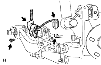
Connect the rear speed sensor connector.
-
Connect the pad wear indicator connector.
-
Install the sensor clamp with the bolt.
8.5 N*m 87 kgf*cm 75 in.*lbf Note:Do not twist the sensor wire when installing the clamps.
-
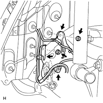
Install the 2 sensor clamps with the 2 nuts.
-
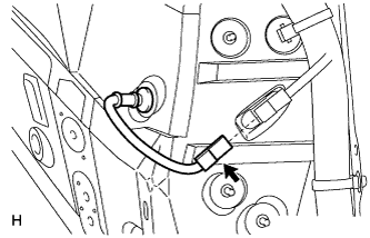
Connect the rear height control sensor connector.
-
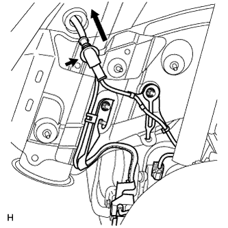
Insert the connector and grommet to the inside of the vehicle through the hole in the wheel house.
-
for RH:
-
Connect the skid control sensor wire connector to the vehicle side connector.
-
-
for LH:
-
Connect the skid control sensor wire connector to the vehicle side connector.
-
-
- Click here
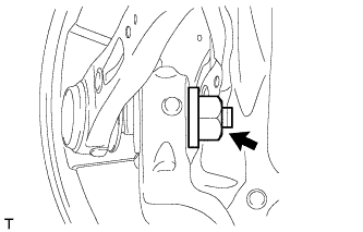
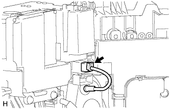
INSTALL LOAD SENSING VALVE SENSOR BRACKET
-
Install the bracket to the toe control link with the bolt.
-
-
Click here
STABILIZE SUSPENSION
-
Install the rear tires.
140 N*m 1428 kgf*cm 103 ft.*lbf -
Lower the vehicle and start the engine. Then fill the pneumatic cylinder assembly with rear shock absorber with air.
-
Lower the vehicle and bounce it up and down several times to stabilize the rear suspension.
-
Remove the rear tires.
-
Jack up the axle carrier with a wooden block between the jack and axle carrier. Apply a load to the suspension so that the rear drive shaft assembly is placed in a horizontal position.
-
- Click here
INSTALL REAR WHEEL
140 N*m 1428 kgf*cm 104 ft.*lbf - Click here
CHECK SUSPENSION CONTROL SYSTEM (for Air suspension)
-
Check the suspension control system (see pageClick here).
-
- Click here
INSPECT AND ADJUST REAR WHEEL ALIGNMENT
-
Inspect and adjust the rear wheel alignment (see pageClick here).
-
- Click here
CHECK SPEED SENSOR SIGNAL
-
Check the speed sensor signal (see pageClick here).
-
- Click here
ADJUST HEADLIGHT ASSEMBLY
-
Adjust the headlight (see pageClick here).
-
- Click here
ADJUST OBJECT RECOGNITION CAMERA
-
Adjust the object recognition camera (see pageClick here).
-