REAR SUSPENSION MEMBER INSTALLATION

-
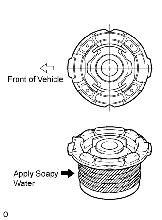
INSTALL REAR SUSPENSION MEMBER BODY MOUNTING CUSHION (for Rear Side)
-
Apply soapy water around the outside of a new rear suspension member body mounting cushion.
-
Position the body mounting cushion as shown in the illustration, and install it to the rear suspension member. Front of Vehicle.
-
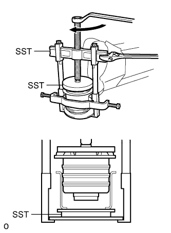
Using SST, press in the body mounting cushion.
- SST
- 09316-12010
- 09570-24011
- 09950-40011 ( 09951-04020, 09952-04010, 09953-04030, 09954-04020, 09955-04051, 09957-04010, 09958-04011 )
- 09950-60020 ( 09951-00910 )
Note
Do not apply excessive force to the inner cylinder of the body mounting cushion. SST
-
-
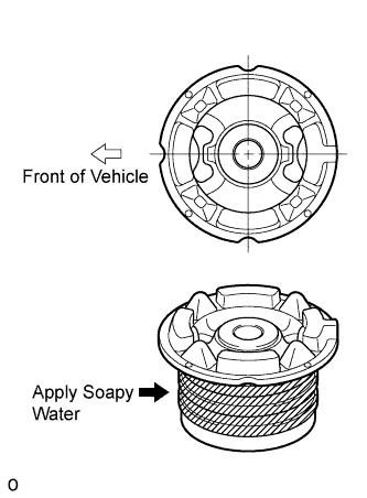
INSTALL REAR SUSPENSION MEMBER BODY MOUNTING CUSHION LH (for Front Side)
-
Apply soapy water around the outside of a new rear suspension member body mounting cushion.
-
Position the body mounting cushion as shown in the illustration, and install it to the rear suspension member.
-
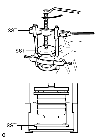
Using SST, press in the body mounting cushion.
- SST
- 09316-12010
- 09570-24011
- 09950-40011 ( 09951-04020, 09952-04010, 09953-04030, 09954-04020, 09955-04051, 09957-04010, 09958-04011 )
- 09950-60020 ( 09951-00910 )
Note
Do not apply excessive force to the inner cylinder of the body mounting cushion. SST
-
-
INSTALL REAR SUSPENSION MEMBER BODY MOUNTING CUSHION RH (for Front Side)
Tech Tips
Use the same procedures described for the LH side.
-
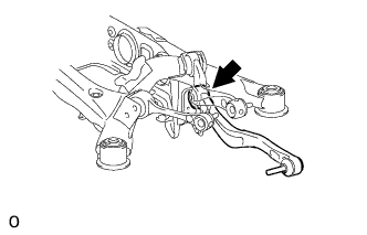
INSTALL REAR NO. 1 DIFFERENTIAL MOUNT CUSHION
-
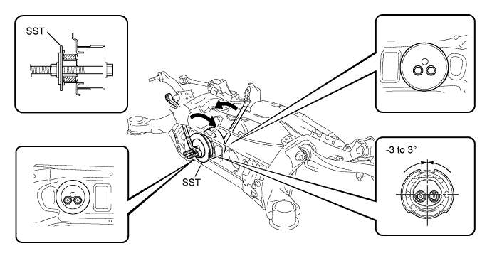
Pass SST bolts through the area shown in the illustration, and install the No. 1 mount cushion.
- SST
- 09570-24011
Note
-
Make sure the mount cushion installation angle misalignment is not over -3 to 3°
-
Make sure the mount cushion is not at an angle by first temporarily installing the mount cushion to the member before installing SST.
-
Before using SST bolts, apply hypoid gear oil to their threads.
-
Be sure to combine SST properly.
-
Confirm that SST contacts the entire seat surface of the mount cushion.
-
Do not install SST bolts at an angle.
-
Make sure SST bolts are tightened equally.
-
-
INSTALL REAR NO. 2 DIFFERENTIAL MOUNT CUSHION
-
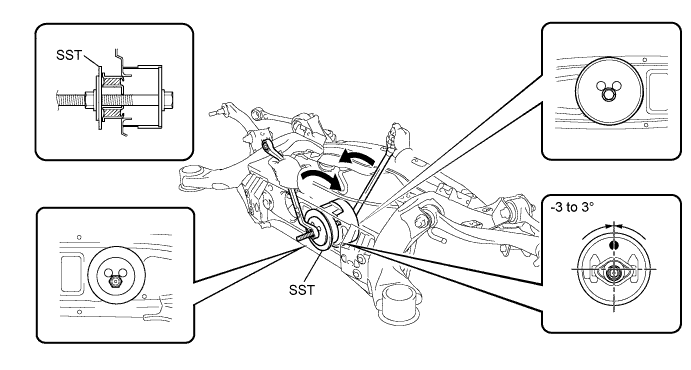
Pass SST bolt through the area shown in the illustration, and install the No. 2 mount cushion.
- SST
- 09570-24011
Note
-
Make sure the mount cushion installation angle misalignment is not over -3 to 3°.
-
Make sure the mount cushion is not at an angle by first temporarily installing the mount cushion to the member before installing SST.
-
Before using SST bolt, apply hypoid gear oil to their threads.
-
Be sure to combine SST properly.
-
Confirm that SST contacts the entire seat surface of the mount cushion.
-
Do not install SST bolts at an angle.
-
-
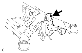
TEMPORARILY INSTALL REAR UPPER NO. 2 CONTROL ARM ASSEMBLY LH
-
Temporarily install the control arm with the bolt, nut and washer to the suspension member.
-
-
TEMPORARILY INSTALL REAR UPPER NO. 2 CONTROL ARM ASSEMBLY RH
Tech Tips
Use the same procedures described for the LH side.
-
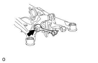
TEMPORARILY INSTALL REAR UPPER NO. 1 CONTROL ARM ASSEMBLY LH
-
Temporarily install the control arm with the bolt, nut and washer to the suspension member.
-
-
TEMPORARILY INSTALL REAR UPPER NO. 1 CONTROL ARM ASSEMBLY RH
Tech Tips
Use the same procedures described for the LH side.
-
TEMPORARILY INSTALL TOE CONTROL LINK SUB-ASSEMBLY LH
-
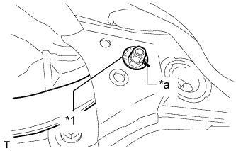
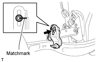
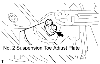
Text in Illustration *1 No. 2 Suspension Toe Adjust Plate *a Matchmark Insert the toe adjust cam from the rear of the vehicle and connect the toe control link. Then temporarily install the No. 2 suspension toe adjust plate with the nut.
Note
Align the matchmarks of the No. 2 suspension toe adjust plate and suspension member.
-
-
TEMPORARILY INSTALL TOE CONTROL LINK SUB-ASSEMBLY RH
Tech Tips
Use the same procedures described for the LH side.
-
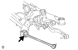
TEMPORARILY INSTALL REAR NO. 1 SUSPENSION ARM ASSEMBLY LH
-
Temporarily install the No. 1 suspension arm with the bolt and nut to the suspension member.
-
-
TEMPORARILY INSTALL REAR NO. 1 SUSPENSION ARM ASSEMBLY RH
Tech Tips
Use the same procedures described for the LH side.
-
INSTALL REAR SUSPENSION MEMBER DAMPER
-
Install the rear suspension member damper with the 3 bolts.
- Torque:
- 25 N*m { 255 kgf*cm, 18 ft.*lbf }
-
-
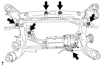
INSTALL REAR ACTIVE STABILIZER CONTROL ACTUATOR ASSEMBLY (w/ Active Stabilizer)
-
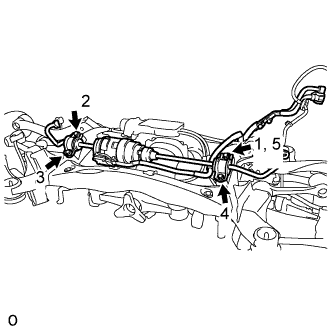
First, temporarily install bolt 1. Then install bolts 2, 3 and 4. Then tighten bolt 5.
- Torque:
- 51 N*m { 520 kgf*cm, 38 ft.*lbf }
-
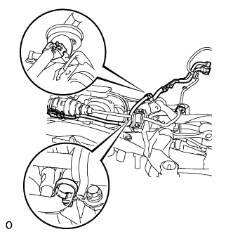
Attach the 2 claws, and install the wire harness to the suspension member.
-
-
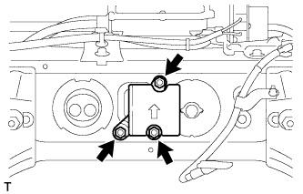
INSTALL REAR STABILIZER BAR (w/o Active Stabilizer)
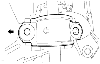
-
Make sure the bracket's arrows face the front of the vehicle.
Text in Illustration 
Front Side -
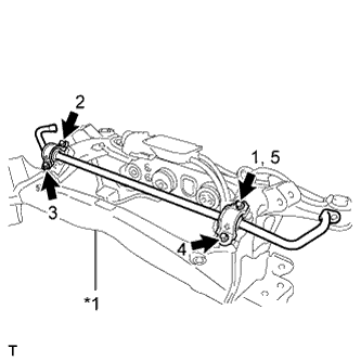
Text in Illustration *1 Rear Suspension Member First, temporarily install bolt 1. Then install bolts 2, 3 and 4. Then tighten bolt 5.
- Torque:
- 51 N*m { 520 kgf*cm, 38 ft.*lbf }
-
-
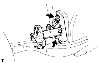
INSTALL PARKING BRAKE WITH BRACKET ACTUATOR ASSEMBLY
-
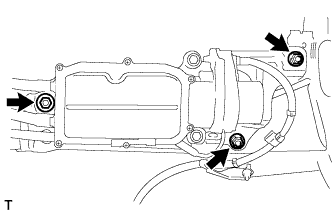
Install the actuator with the 3 nuts.
- Torque:
- 27 N*m { 275 kgf*cm, 20 ft.*lbf }
-
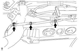
Install the 3 harness clamps to the member.
-
Install the bolt and 5 nuts.
- Torque:
- 8.0 N*m { 82 kgf*cm, 71 in.*lbf }
-
Attach the clamp to the member.
-
-
INSTALL REAR STABILIZER LINK ASSEMBLY LH
-
Install the stabilizer link with the nut to the stabilizer bar.
- Torque:
- 89 N*m { 908 kgf*cm, 66 ft.*lbf }
-
-
INSTALL REAR STABILIZER LINK ASSEMBLY RH
Tech Tips
Use the same procedures described for the LH side.
-
INSTALL REAR SUSPENSION MEMBER SUB-ASSEMBLY
-
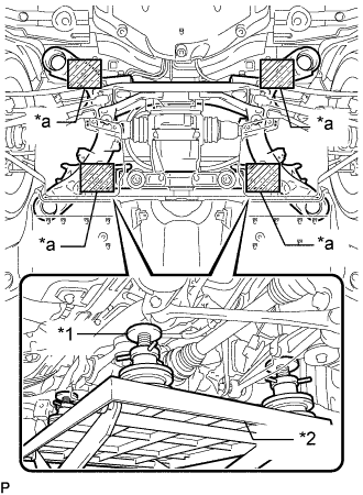
Text in Illustration *1 Attachment *2 Engine Lifter *a Attachment placement location Support the rear suspension member sub-assembly with an engine lifter using 4 attachments or equivalent tools.
Note
-
Make sure to secure the rear suspension member sub-assembly to prevent it from dropping.
-
Use the attachments to keep the rear suspension member sub-assembly level.
-
The rear suspension member sub-assembly is a heavy component. Make sure that it is supported securely.
-
-
Raise the rear suspension member sub-assembly until there is no clearance between the rear suspension member sub-assembly and the body.
Note
When raising the rear suspension member subassembly, be careful not to damage the vehicle body or other components installed on the vehicle.
-
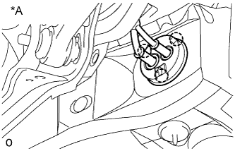
Text in Illustration *A w/ Active Stabilizer w/ Active Stabilizer:
-
Attach the 3 claws to install the wire harness grommet of the active stabilizer control actuator.
Tech Tips
Install the grommet so that the arrow of the grommet is facing the top of the vehicle.
-
-
for Sports Package:
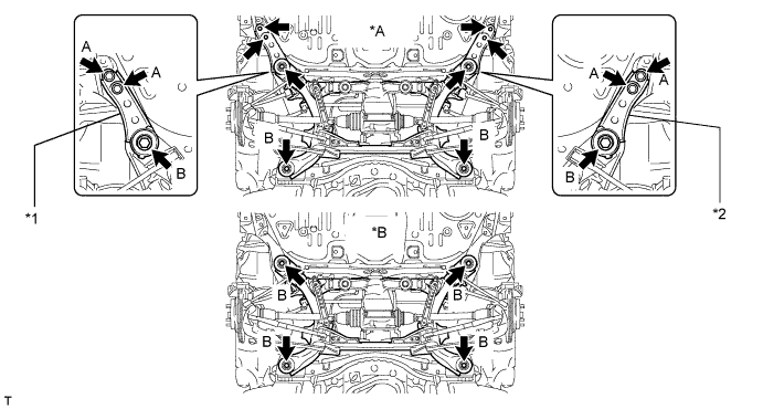
Text in Illustration *A for Sports Package *B for Standard *1 Suspension Member Stopper Lower RH *2 Suspension Member Stopper Lower LH
-
Install the 2 member stoppers with the 4 bolts labeled B, and install the 4 bolts labeled A.
- Torque:
- for bolt A
- 19 N*m { 194 kgf*cm, 14 ft.*lbf }
- for bolt B
- 127 N*m { 1295 kgf*cm, 94 ft.*lbf }
-
-
for Standard:
-
Install the 4 bolts labeled B.
- Torque:
- 127 N*m { 1295 kgf*cm, 94 ft.*lbf }
-
-
-
INSTALL REAR DIFFERENTIAL CARRIER ASSEMBLY WITH DRIVE SHAFT
-
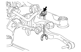
INSTALL LOAD SENSING VALVE SENSOR BRACKET
-
Install the bracket to the toe control link with the bolt.
-
-
INSTALL REAR HEIGHT CONTROL SENSOR SUB-ASSEMBLY LH
-
Install the height control sensor with the 2 bolts.
- Torque:
- 14 N*m { 138 kgf*cm, 10 ft.*lbf }
Note
Do not drop the height control sensor. If it is dropped, replace it with a new one.
-
Align the matchmarks on the height control sensor link and bracket.
-
Install the nut to the height control sensor link.
- Torque:
- 5.3 N*m { 54 kgf*cm, 47 in.*lbf }
-
Connect the connector.
-
-
INSTALL REAR HEIGHT CONTROL SENSOR SUB-ASSEMBLY RH
Tech Tips
Use the same procedures described for the LH side.
-
INSTALL PROPELLER SHAFT WITH CENTER BEARING ASSEMBLY
-
INSTALL REAR AXLE ASSEMBLY LH
-
INSTALL REAR AXLE ASSEMBLY RH
Tech Tips
Use the same procedures described for the LH side.
-
INSTALL ELECTRIC PARKING BRAKE ACTUATOR CAP
-
CONNECT ELECTRIC PARKING BRAKE ACTUATOR CONNECTOR
-
CONNECT REAR ACTIVE STABILIZER CONTROL ACTUATOR CONNECTOR (w/ Active Stabilizer)
-
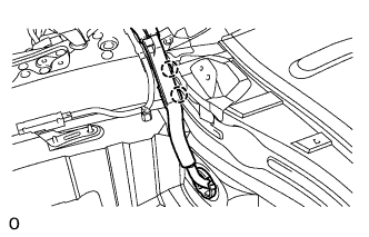
Attach the 2 clamps to install the wire harness to the body.
-
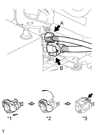
Connect the actuator connector labeled A.
-
Connect the actuator connector labeled B.
-
Connect the actuator connector. (*1)
-
Rotate the lever in the direction of the arrow until a "click" sound is heard. (*2)
-
Lock the lever's lock. (*3)
-
-
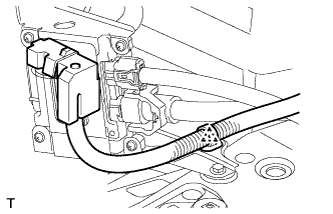
Attach the wire harness clamp to the bracket.
-
-
INSTALL LUGGAGE COMPARTMENT TRIM COVER ASSEMBLY LH
-
INSTALL REAR WHEEL HOUSE LINER LH
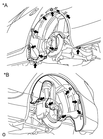
Text in Illustration *1 Front Side *2 Rear Side
-
Install the liner with the 3 screws, 11 nuts, 2 clips to the vehicle side.
-
-
INSTALL REAR WHEEL HOUSE LINER RH
Tech Tips
Use the same procedures described for the LH side.
-
STABILIZE SUSPENSION
-
Install the rear tires.
- Torque:
- 140 N*m { 1428 kgf*cm, 103 ft.*lbf }
-
Lower the vehicle and start the engine. Then fill the pneumatic cylinder assembly with rear shock absorber with air.
-
Lower the vehicle and bounce it up and down several times to stabilize the rear suspension.
-
Remove the rear tires.
-
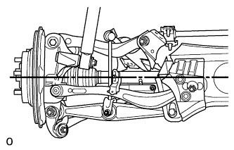
Jack up the axle carrier with a wooden block between the jack and axle carrier. Apply a load to the suspension so that the rear drive shaft assembly is placed in a horizontal position.
-
-
TIGHTEN REAR NO. 2 SUSPENSION ARM ASSEMBLY LH
-
Tighten the nut.
- Torque:
- 150 N*m { 1530 kgf*cm, 111 ft.*lbf }
-
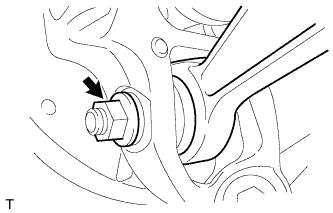
Tighten the nut.
- Torque:
- 225 N*m { 2294 kgf*cm, 166 ft.*lbf }
-
-
TIGHTEN REAR NO. 2 SUSPENSION ARM ASSEMBLY RH
Tech Tips
Use the same procedures described for the LH side.
-
TIGHTEN PNEUMATIC CYLINDER WITH REAR SHOCK ABSORBER ASSEMBLY LH
-
Tighten the nut on the axle carrier.
- Torque:
- 80 N*m { 816 kgf*cm, 59 ft.*lbf }
-
-
TIGHTEN PNEUMATIC CYLINDER WITH REAR SHOCK ABSORBER ASSEMBLY RH
Tech Tips
Use the same procedures described for the LH side.
-
INSPECT REAR UPPER NO. 1 CONTROL ARM BALL JOINT LOOSENESS
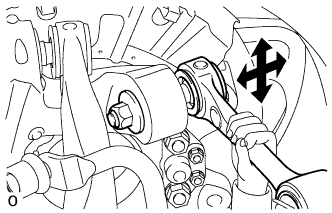
-
Jack up the vehicle.
-
Shake the suspension arm by hand and check for looseness.
OK No looseness is felt
-
-
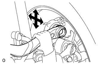
INSPECT REAR UPPER NO. 2 CONTROL ARM BALL JOINT LOOSENESS
-
Jack up the vehicle.
-
Shake the suspension arm by hand and check for looseness.
OK No looseness is felt
-
-
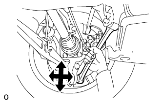
INSPECT REAR NO. 1 SUSPENSION ARM BALL JOINT LOOSENESS
-
Jack up the vehicle.
-
Shake the suspension arm by hand and check for looseness.
OK No looseness is felt
-
-
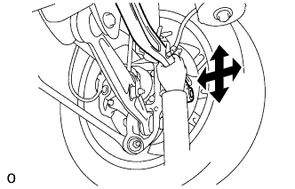
INSPECT TOE CONTROL LINK BALL JOINT LOOSENESS
-
Jack up the vehicle.
-
Shake the suspension link by hand and check for looseness.
OK No looseness is felt
-
-
INSTALL REAR WHEEL
- Torque:
- 140 N*m { 1428 kgf*cm, 103 ft.*lbf }
-
CHECK SUSPENSION CONTROL SYSTEM
-
INSPECT AND ADJUST REAR WHEEL ALIGNMENT
-
ADJUST HEADLIGHT ASSEMBLY
-
ADJUST OBJECT RECOGNITION CAMERA