FRONT LOWER SUSPENSION ARM REMOVAL

Tech Tips
-
Use the same procedures for the RH side and LH side.
-
The procedures listed below are for the LH side.
-
REMOVE FRONT WHEEL
-
REMOVE FRONT AXLE SHAFT NUT LH
-
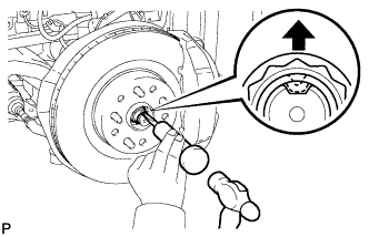
Using SST and a hammer, release the staked part of the front axle shaft nut.
- SST
- 09930-00010
Note
Release the staked part of the nut completely, otherwise the threads of the drive shaft may be damaged.
-
While applying the brakes, remove the front axle shaft nut.
-
-
DISCONNECT FRONT DISC BRAKE CALIPER ASSEMBLY LH
-
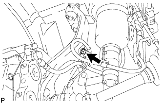
Remove the bolt and disconnect the flexible hose from the steering knuckle.
-
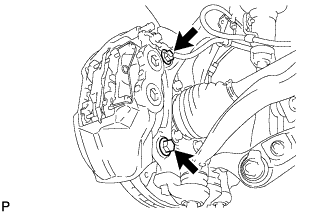
Remove the 2 bolts and disconnect front disc brake caliper.
Note
-
Hang the front disc brake caliper assembly with a rope or wire.
-
Do not damage the brake hose.
-
-
-
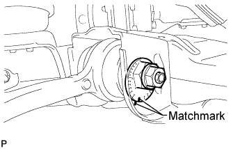
REMOVE FRONT DISC
-
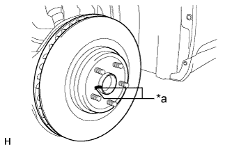
Text in Illustration *a Matchmark Remove the front disc from the front axle hub.
Tech Tips
Put matchmarks on the disc and axle hub.
-
-
REMOVE FRONT DISC BRAKE DUST COVER LH
-
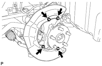
Remove the 4 bolts and dust cover.
-
-
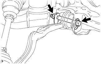
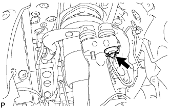
DISCONNECT FRONT HEIGHT CONTROL SENSOR SUB-ASSEMBLY LH
-
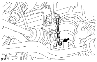
Remove the nut, and then remove the bracket of the front height control sensor LH.
-
-
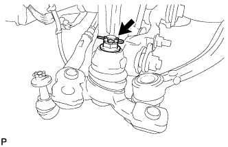
REMOVE FRONT NO. 2 SUSPENSION LOWER ARM LH
-
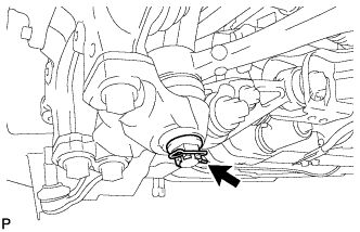
Remove the clip and nut.
-
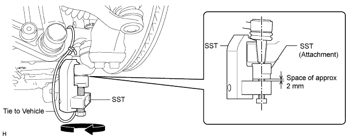
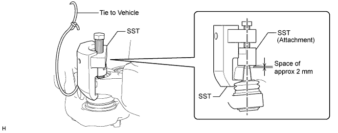
Install SST (attachment) to the front No. 2 suspension lower arm so that there is a space of approximately 2 mm (0.0787 in.) between the front No. 2 suspension lower arm and attachment.
- SST
- 09628-50010 ( 09628-05010 )
Note
As SST may become damaged, make sure the space between the front No. 2 suspension lower arm and attachment is not 2 mm (0.0787 in.) or less.
-
Using SST, remove the front No. 2 suspension lower arm from the lower ball joint assembly.
- SST
- 09628-50010 ( 09628-05010 )
Note
-
Apply molybdenum grease to the threads and end of the SST bolt.
-
Do not damage the dust cover of the front No. 2 suspension lower arm.
-
Make sure that the bolt of SST and the front No. 2 suspension lower arm are in a straight line when installing SST.
-
Be sure to tie the string of SST to the vehicle to prevent SST from dropping.
-
Do not apply a torque of 160 N*m (1631 kgf*cm, 118 ft.*lbf) or more to SST as it may be damaged.
-
Put matchmarks on the front suspension toe adjusting cam and front frame assembly.
-
Put matchmarks on the front suspension No. 2 toe adjusting plate and front frame assembly.
-
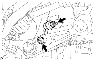
Remove the nut, front suspension No. 2 toe adjusting plate and bolt.
-
Remove the front suspension toe adjusting cam and the front suspension lower arm LH.
-
-
DISCONNECT SKID CONTROL SENSOR WIRE
-
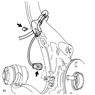
Disconnect the front speed sensor connector.
Note
Do not twist the skid control sensor wire.
-
Remove the bolt and sensor clamp.
-
-
REMOVE FRONT SPEED SENSOR LH
-
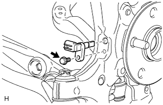
Remove the bolt and speed sensor from the steering knuckle.
Note
-
Do not damage the tip of the speed sensor.
-
Do not allow foreign matter to contact the tip or installation area of the speed sensor.
-
-
-
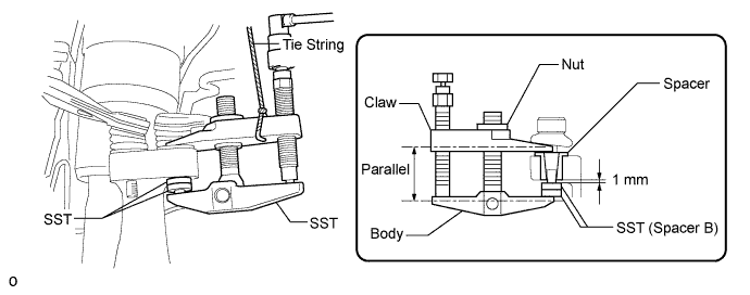
DISCONNECT TIE ROD ASSEMBLY LH
-
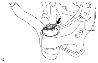
Remove the clip and nut.
-
Install 2 spacers (SST spacer B) onto the tie rod assembly LH so that there is a space of approximately 1 mm (0.0394 in.) between the arm and spacers.
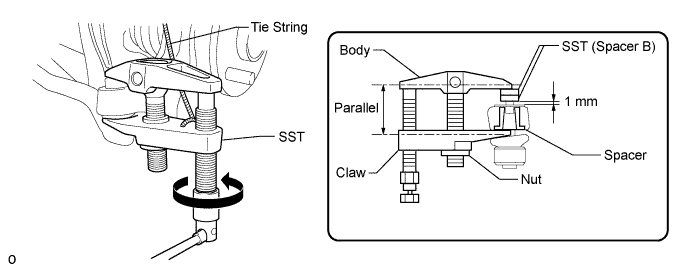
- SST
- 09960-20010 ( 09961-02060 )
Note
-
Make sure to install the spacers (SST spacer B) as the steering knuckle spacer may shift.
-
As SST may become damaged, make sure the space between the arm and spacers is not less than 1 mm (0.0394 in.).
-
Using SST, disconnect the tie rod assembly from the steering knuckle.
- SST
- 09960-20010 ( 09961-02010 )
Note
-
Apply molybdenum grease to the threads and end of the SST bolt.
-
Do not damage the dust cover.
-
As the dust cover may be damaged, adjust SST with the center nut so that the body and claw are the parallel.
-
Make sure to tie the string of SST to the vehicle to prevent SST from dropping.
-
-
DISCONNECT FRONT NO. 1 SUSPENSION UPPER ARM ASSEMBLY LH
-
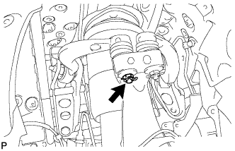
Remove the clip and nut.
-
Install 2 spacers (SST spacer B) onto the front No. 1 suspension upper arm assembly LH so that there is a space of approximately 1 mm (0.0394 in.) between the arm and spacers.
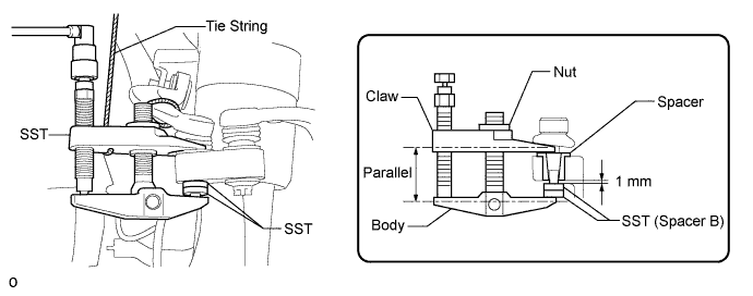
- SST
- 09960-20010 ( 09961-02060 )
Note
-
Make sure to install the spacers (SST spacer B) as the steering knuckle spacer may shift.
-
As SST may become damaged, make sure the space between the arm and spacers is not less than 1 mm (0.0394 in.).
-
Using SST, disconnect the front No. 1 suspension upper arm from the steering knuckle.
- SST
- 09960-20010 ( 09961-02010 )
Note
-
Apply molybdenum grease to the threads and end of the SST bolt.
-
Do not damage the dust cover.
-
As the dust cover may be damaged, adjust SST with the center nut so that the body and claw are parallel.
-
Make sure to tie the string of SST to the vehicle to prevent SST from dropping.
-
-
DISCONNECT FRONT NO. 2 SUSPENSION UPPER ARM ASSEMBLY LH
-
Remove the clip and nut.
-
Install 2 spacers (SST spacer B) onto the front No. 2 suspension upper arm assembly LH so that there is a space of approximately 1 mm (0.0394 in.) between the arm and spacers.
- SST
- 09960-20010 ( 09961-02060 )
Note
-
Make sure to install the spacers (SST spacer B) as the steering knuckle spacer may shift.
-
As SST may become damaged, make sure the space between the arm and spacers is not less than 1 mm (0.0394 in.).
-
Using SST, disconnect the front No. 2 suspension upper arm from the steering knuckle.
- SST
- 09960-20010 ( 09961-02010 )
Note
-
Apply molybdenum grease to the threads and end of the SST bolt.
-
Do not damage the dust cover.
-
As the dust cover may be damaged, adjust SST with the center nut so that the body and claw are parallel.
-
Make sure to tie the string of SST to the vehicle to prevent SST from dropping.
-
-
REMOVE STEERING KNUCKLE LH
-
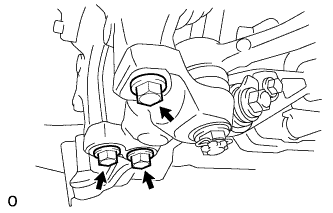
Remove the 3 bolts. Then disconnect the steering knuckle from the front lower ball joint.
-
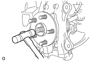
Using a plastic-faced hammer, lightly tap the end of the front drive shaft to remove the front axle hub and steering knuckle from the front drive shaft.
Tech Tips
If the spline connection is tight, using a brass bar and hammer, tap the front drive shaft.
-
While supporting the drive shaft, remove the steering knuckle LH.
Note
-
Do not damage the drive shaft outboard joint boot.
-
Suspend the drive shaft assembly with a rope or wire.
-
Be careful when handling or installing the drive shaft as bending or sliding the drive shaft excessively may cause the tripod joint to come out of its groove.
-
-
-
REMOVE FRONT LOWER BALL JOINT ASSEMBLY LH
-
Remove the clip and nut.
-
Install SST (attachment) to the front lower ball joint so that there is a space of approximately 2 mm (0.0787 in.) between the front lower ball joint and attachment.
- SST
- 09628-50010 ( 09628-05010 )
Note
-
As SST may become damaged, make sure the front lower ball joint between the arm and attachment is not 2 mm (0.0787 in.) or less.
-
Be sure to install SST (attachment) in order to prevent damage to the lower ball joint stud.
-
Using SST, remove the lower ball joint from the front suspension lower arm.
- SST
- 09628-50010 ( 09628-05010 )
Note
-
Apply molybdenum grease to the threads and end of the SST bolt.
-
Do not damage the dust cover of the lower arm.
-
Make sure that the bolt of SST and the front No. 2 suspension lower arm are in a straight line when installing SST.
-
Be sure to tie the string of SST to the vehicle to prevent SST from dropping.
-
Do not apply a torque of 160 N*m (1631 kgf*cm, 118 ft.*lbf) or more to SST as it may be damaged.
-
-
REMOVE FRONT STABILIZER LINK ASSEMBLY LH
-
Remove the 2 nuts and front stabilizer link.
Tech Tips
If the ball joint turns together with the nut, use a 6 mm hexagon wrench to hold the stud bolt.
-
-
DISCONNECT FRONT SHOCK ABSORBER LOWER BRACKET SUB-ASSEMBLY LH
-
Remove the nut and front shock absorber upper bracket plate, and disconnect the front shock absorber lower bracket from the front suspension lower arm LH.
-
-
REMOVE FRONT SUSPENSION LOWER ARM ASSEMBLY LH

-
Put matchmarks on the camber adjusting cam and front frame assembly.
-
Put matchmarks on the No. 2 camber adjusting cam and front frame assembly.
-
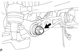
Remove the nut and No. 2 camber adjusting cam.
-
Remove the camber adjusting cam and front suspension lower arm LH.
-