REAR SUSPENSION MEMBER REMOVAL

-
REMOVE REAR WHEEL
-
REMOVE REAR WHEEL HOUSE LINER LH
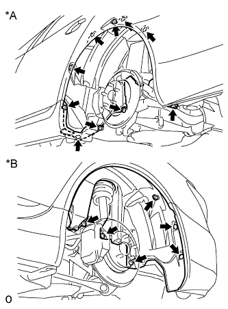
Text in Illustration *A Front Side *B Rear Side
-
Remove the 4 screws, 11 nuts and 2 clips from the liner.
-
-
REMOVE REAR WHEEL HOUSE LINER RH
Tech Tips
Use the procedures described for the LH side.
-
REMOVE LUGGAGE COMPARTMENT TRIM COVER ASSEMBLY LH
-
DISCONNECT REAR ACTIVE STABILIZER CONTROL ACTUATOR CONNECTOR (w/ Active Stabilizer)
-
DISCONNECT ELECTRIC PARKING BRAKE ACTUATOR CONNECTOR
-
REMOVE ELECTRIC PARKING BRAKE ACTUATOR CAP
-
REMOVE REAR AXLE ASSEMBLY LH
-
REMOVE REAR AXLE ASSEMBLY RH
Tech Tips
Use the procedures described for the LH side.
-
REMOVE PROPELLER SHAFT WITH CENTER BEARING ASSEMBLY
-
REMOVE REAR DIFFERENTIAL CARRIER ASSEMBLY WITH DRIVE SHAFT
-
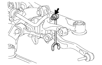
REMOVE REAR HEIGHT CONTROL SENSOR SUB-ASSEMBLY LH
-
Disconnect the connector.
-
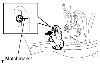
Place matchmarks on the height control sensor link and bracket.
-
Remove the nut and disconnect the height control sensor link from the bracket.
-
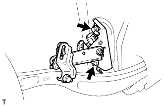
Remove the 2 bolts and height control sensor from the rear suspension member.
Note
Do not drop the height control sensor. If it is dropped, replace it with a new one.
-
-
REMOVE REAR HEIGHT CONTROL SENSOR SUB-ASSEMBLY RH
Tech Tips
Use the procedures described for the LH side.
-
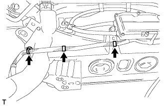
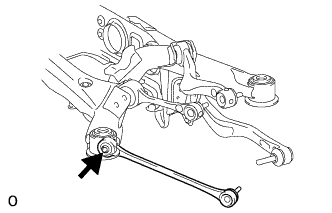
REMOVE LOAD SENSING VALVE SENSOR BRACKET
-
Remove the bolt and bracket from the toe control link.
-
-
REMOVE REAR SUSPENSION MEMBER SUB-ASSEMBLY
-
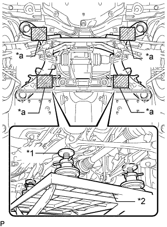
Text in Illustration *1 Attachment *2 Engine Lifter *a Attachment placement location Support the rear suspension member sub-assembly with an engine lifter using 4 attachments or equivalent tools as shown in the illustration.
Note
-
Use the attachments to keep the rear suspension member sub-assembly level.
-
The rear suspension member sub-assembly is a heavy component. Make sure that it is supported securely.
-
-
for Sports Package:
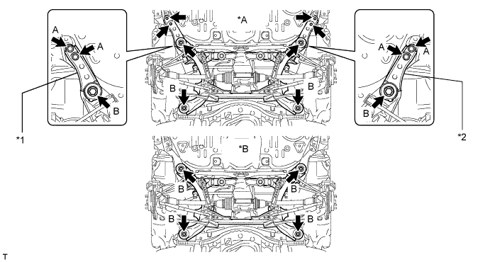
Text in Illustration *A for Sports Package *B for Standard *1 Suspension Member Stopper Lower RH *2 Suspension Member Stopper Lower LH
-
Remove the 4 bolts labeled A.
-
Remove the 4 bolts labeled B and 2 suspension member stoppers.
-
Slowly lower the rear suspension member subassembly.
Note
When lowering the rear suspension member sub-assembly, be careful not to damage the vehicle body or other components installed on the vehicle.
-
-
for Standard:
-
Remove the 4 bolts.
-
Slowly lower the rear suspension member subassembly.
Note
When lowering the rear suspension member sub-assembly, be careful not to damage the vehicle body or other components installed on the vehicle.
-
-
-
REMOVE REAR STABILIZER LINK ASSEMBLY LH
-
Remove the nut and disconnect the stabilizer link from the stabilizer bar.
Tech Tips
If the ball joint turns together with the nut, use a 6 mm hexagon wrench to hold the stud.
-
-
REMOVE REAR STABILIZER LINK ASSEMBLY RH
Tech Tips
Use the same procedures described for the LH side.
-
REMOVE PARKING BRAKE WITH BRACKET ACTUATOR ASSEMBLY
-
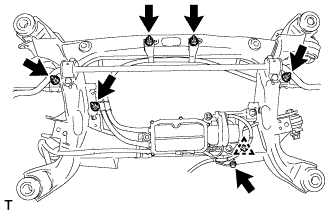
Remove the bolt and 5 nuts.
-
Detach the clamp from the member.
-
Remove the 3 harness clamps from the member.
-
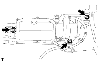
Remove the 3 nuts and actuator.
-
-
REMOVE REAR STABILIZER BAR (w/o Active Stabilizer)
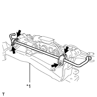
Text in Illustration *1 Rear Suspension Member
-
Remove the 4 bolts and stabilizer bar from the suspension member.
Tech Tips
The stabilizer bracket and bush are built onto the stabilizer bar. If the bracket and/or bush detach from the bar, replace the bar.
-
-
REMOVE REAR ACTIVE STABILIZER CONTROL ACTUATOR ASSEMBLY (w/ Active stabilizer)
-
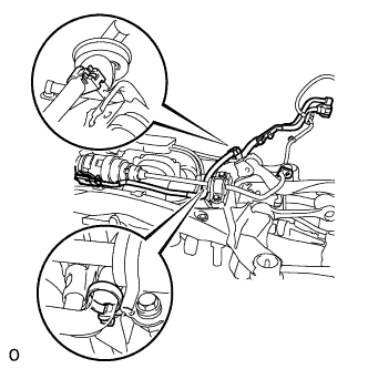
Disconnect the 2 claws, and remove the wire harness from the suspension member.
-
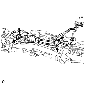
Remove the 4 bolts and active stabilizer from the suspension member.
-
-
REMOVE REAR SUSPENSION MEMBER DAMPER
-
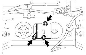
Remove the 3 bolts, and the rear suspension member damper.
-
-
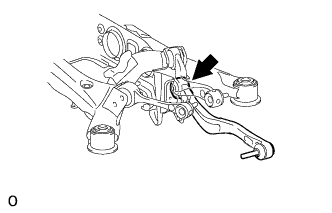
REMOVE REAR NO. 1 SUSPENSION ARM ASSEMBLY LH
-
Remove the bolt, nut and No. 1 suspension arm from the suspension member.
-
-
REMOVE REAR NO. 1 SUSPENSION ARM ASSEMBLY RH
Tech Tips
Use the same procedures described for the LH side.
-
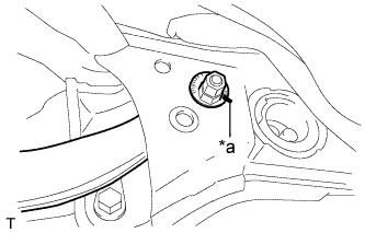
REMOVE TOE CONTROL LINK SUB-ASSEMBLY LH
-
Place matchmarks on the No. 2 suspension toe adjust plate and suspension member.
Text in Illustration *a Matchmark -
Remove the nut, No. 2 toe adjust plate, toe adjust cam and toe control link from the suspension member.
-
-
REMOVE TOE CONTROL LINK SUB-ASSEMBLY RH
Tech Tips
Use the same procedures described for the LH side.
-
REMOVE REAR UPPER NO. 1 CONTROL ARM ASSEMBLY LH
-
Remove the nut, washer, bolt and control arm from the rear suspension member.
-
-
REMOVE REAR UPPER NO. 1 CONTROL ARM ASSEMBLY RH
Tech Tips
Use the same procedures described for the LH side.
-
REMOVE REAR UPPER NO. 2 CONTROL ARM ASSEMBLY LH
-
Remove the nut, washer, bolt and rear control arm from the rear suspension member.
-
-
REMOVE REAR UPPER NO. 2 CONTROL ARM ASSEMBLY RH
Tech Tips
Use the same procedures described for the LH side.
-
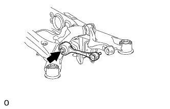
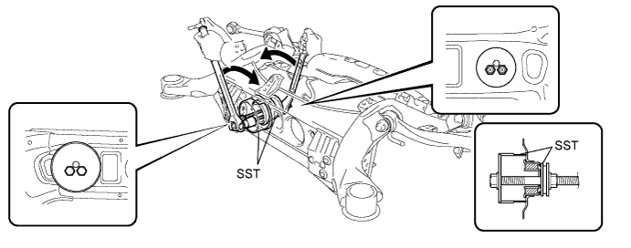
REMOVE REAR NO. 1 DIFFERENTIAL MOUNT CUSHION
-
Pass SST bolts through the area shown in the illustration, and remove the No. 1 mount cushion.
- SST
- 09316-12010
- 09570-24011
Note
-
When removing the No. 1 mount cushion, do not allow the rear suspension member to contact SST (09316-12010).
-
Before using SST bolts, apply hypoid gear oil to their threads.
-
Be sure to combine SST properly.
-
Do not install SST bolts at an angle.
-
Make sure SST bolts are tightened equally.
-
-
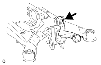
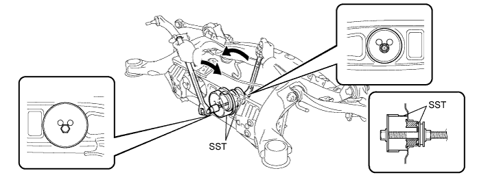
REMOVE REAR NO. 2 DIFFERENTIAL MOUNT CUSHION
-
Pass SST bolt through the area shown in the illustration, and remove the No. 2 mount cushion.
- SST
- 09316-12010
- 09570-24011
Note
-
When removing the No. 2 mount cushion, do not allow the rear suspension member to contact SST (09316-12010).
-
Before using SST bolt, apply hypoid gear oil to its threads.
-
Be sure to combine SST properly.
-
Do not install SST bolts at an angle.
-
-
REMOVE REAR SUSPENSION MEMBER BODY MOUNTING CUSHION LH (for Front Side)
-
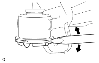
Using a chisel, widen the area between the rear suspension member and the body mounting cushion enough for the claws of SST.
-
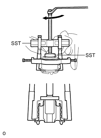
Using SST, remove the rear suspension member body mounting cushion.
- SST
- 09950-40011 ( 09951-04020, 09952-04010, 09953-04030, 09954-04020, 09957-04010, 09958-04011 )
- 09950-60010 ( 09951-00540 )
Note
-
Be careful as the rear suspension member body mounting cushion may come out with force.
-
Do not reuse the removed rear suspension body mounting cushion.
-
If the outer cylinder of the rear suspension member body mounting cushion remains, insert SST into the gaps between the rear suspension member and the body mounting cushion and remove it.
-
Cut off the mounting cushion until SST can be set.
-
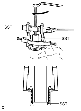
Using SST, remove the outer cylinder of the body mounting cushion.
- SST
- 09608-06041
- 09950-40011 ( 09951-04020, 09952-04010, 09953-04030, 09954-04020, 09957-04010, 09958-04011 )
- 09950-60010 ( 09951-00540 )
- 09950-60020 ( 09951-00680 )
-
-
-
REMOVE REAR SUSPENSION MEMBER BODY MOUNTING CUSHION RH (for Front Side)
Tech Tips
Use the same procedures described for the LH side.
-
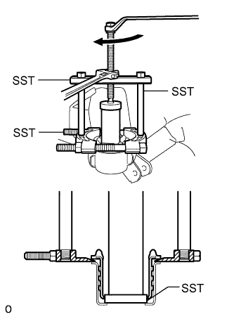
REMOVE REAR SUSPENSION MEMBER BODY MOUNTING CUSHION (for Rear Side)
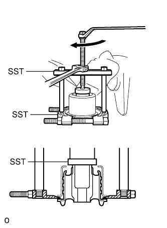
-
Using SST, remove the rear suspension member body mounting cushion.
- SST
- 09950-00020
- 09950-00030
- 09950-40011 ( 09957-04010 )
- 09950-60010 ( 09951-00540 )
Note
-
Be careful as the rear suspension member body mounting cushion may come out with force.
-
Do not reuse the removed rear suspension body mounting cushion.
-
If the outer cylinder of the rear suspension member body mounting cushion remains, insert SST into the gaps between the rear suspension member and the body mounting cushion and remove it. SST
-
Cut off the mounting cushion until SST can be set.
-
Using SST, remove the outer cylinder of the body mounting cushion.
- SST
- 09608-06041
- 09950-00020
- 09950-00030
- 09950-60020
-
-