FRONT ACTIVE STABILIZER CONTROL ECU INSTALLATION

-
INSTALL BRACKET
-
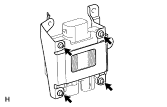
Install the bracket with the 4 screws.
- Torque:
- 3.0 N*m { 31 kgf*cm, 27 in.*lbf }
-
-
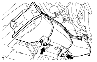
INSTALL FRONT ACTIVE STABILIZER CONTROL ECU
-

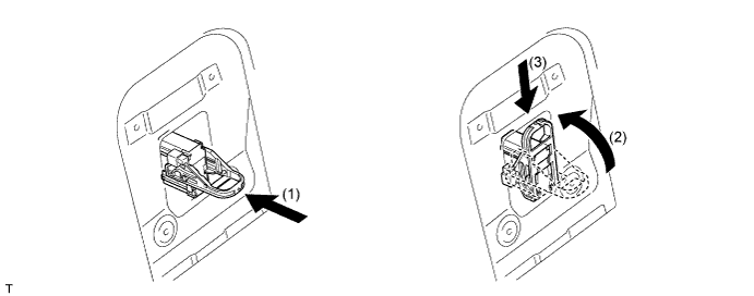
Connect the ECU connector.
-
Connect the ECU connector. (*1)
-
Rotate the lever in the direction of the arrow until a "click" sound is heard. (*2)
-
Lock the lever's lock. (*3)
-
-
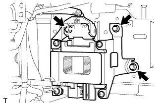
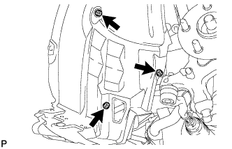
Install the ECU with the 3 bolts.
- Torque:
- 14 N*m { 138 kgf*cm, 10 ft.*lbf }
-
-
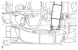
CONNECT FRONT ACTIVE STABILIZER CONTROL ACTUATOR CONNECTOR
-
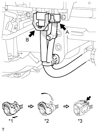
Connect the actuator connector labeled A.
-
Connect the actuator connector labeled B.
-
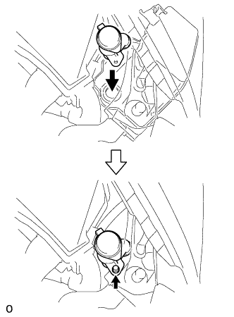
Connect the actuator connector. (*1)
-
Rotate the lever in the direction of the arrow until a "click" sound is heard. (*2)
-
Lock the lever's lock. (*3)
-
-
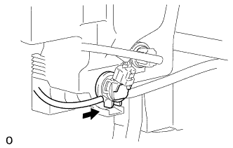
Connect the wire harness clamp.
-
-
INSTALL INLET ENGINE ROOM ECM DUCT
-
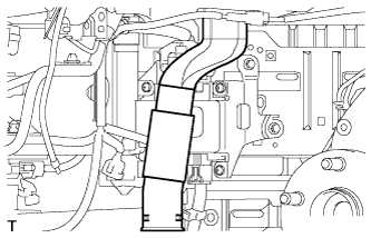
Install the duct.
-
-
INSTALL NO. 3 COOL AIR INTAKE DUCT SUB-ASSEMBLY
-
Attach the 2 claws.
-
Attach the clamp.
-
Install the duct with the 2 bolts.
- Torque:
- 5.4 N*m { 55 kgf*cm, 48 in.*lbf }
-
-
INSTALL WINDSHIELD WASHER JAR ASSEMBLY
-
Attach the guide to install the windshield washer jar and pump with the 3 bolts.
- Torque:
- 5.5 N*m { 56 kgf*cm, 49 in.*lbf }

-
Connect the 3 connectors and attach the 4 clamps.
-
-
INSTALL WASHER INLET SUB-ASSEMBLY
-
Install the washer inlet with the bolt.
- Torque:
- 5.5 N*m { 56 kgf*cm, 49 in.*lbf }
-
-
FILL WINDSHIELD WASHER JAR AND PUMP ASSEMBLY WITH WASHER FLUID
-
Connect the washer hose to the windshield washer motor and pump, and fill the washer jar with washer fluid.
-
-
INSTALL HEADLIGHT ASSEMBLY LH
-
CONNECT FRONT FENDER LINER LH
-
Install the liner with the 3 screws.
-
-
INSTALL NO. 1 ENGINE UNDER COVER
-
Install the under cover with the 9 screws and 7 clips.
-
-
INSTALL FRONT BUMPER COVER
-
INSTALL SERVICE PLUG GRIP
CAUTION:
Be sure to wear insulated gloves.
-
Wear insulated gloves and insert the service plug grip.
-
Turn the lever of the service plug grip 90° and slide the service plug grip downward until a click sound is heard.
-
-
INSTALL SERVICE PLUG COVER
-
Install the service plug cover with the 4 bolts.
- Torque:
- 7.5 N*m { 76 kgf*cm, 66 in.*lbf }
-
-
CONNECT CABLE TO AUXILIARY BATTERY NEGATIVE TERMINAL
Note
When disconnecting the cable, some systems need to be initialized after the cable is reconnected Click here.
-
INSTALL BATTERY SERVICE HOLE COVER LH
-

Text in Illustration *A for Standard *B for Ottoman Attach the battery service hole cover LH with the clip and fastening tape.
-
-
INSTALL LUGGAGE COMPARTMENT MAT SUB-ASSEMBLY

-
CHECK SRS WARNING LIGHT
-
ADJUST HEADLIGHT ASSEMBLY