FRONT ACTIVE STABILIZER CONTROL ECU REMOVAL

Note
After turning the power switch off, waiting time may be required before disconnecting the cable from the auxiliary battery terminal. Therefore, make sure to read the disconnecting the cable from the auxiliary battery terminal notice before proceeding with work Click here.
-
REMOVE LUGGAGE COMPARTMENT MAT SUB-ASSEMBLY

-
REMOVE BATTERY SERVICE HOLE COVER LH
-

Text in Illustration *A for Standard *B for Ottoman *1 Fastening Tape Detach the clip, fastening tape and remove the battery service hole cover LH.
-
-
DISCONNECT CABLE FROM AUXILIARY BATTERY NEGATIVE TERMINAL
CAUTION:
Wait at least 90 seconds after disconnecting the cable from the negative (-) battery terminal to prevent airbag and seat belt pretensioner activation.
Note
When disconnecting the cable, some systems need to be initialized after the cable is reconnected Click here.
-
REMOVE SERVICE PLUG COVER
-
Remove the 4 bolts and service plug cover.
-
-
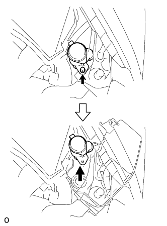
REMOVE SERVICE PLUG GRIP
CAUTION:
-
Remove the service plug grip to interrupt a high voltage circuit at the time of the check.
-
Keep the removed service plug grip in your pocket to prevent other technicians from accidentally reconnecting it while you are servicing the vehicle.
-
All the high voltage wiring connectors are orange colored.
-
Wear insulated gloves. Slide the service plug grip upward, turn the lever downward, and then remove the service plug grip.
CAUTION:
After disconnecting the service plug grip, wait for at least 10 minutes before touching any of the high-voltage connectors or terminals.
Note
Never turn the power switch on (READY) with the service plug grip removed as malfunctions may occur.
Tech Tips
Waiting for at least 10 minutes is required to discharge the high-voltage capacitor inside the inverter with converter assembly.
-
-
REMOVE FRONT BUMPER COVER
-
REMOVE NO. 1 ENGINE UNDER COVER
-
Remove the 9 screws, 7 clips and under cover.
-
-
DISCONNECT FRONT FENDER LINER LH
-
Remove the 3 screws.
-
Partially remove the fender liner.
Tech Tips
It is not necessary to fully remove the fender liner. Partially remove it so that the ECU can be removed.
-
-
REMOVE HEADLIGHT ASSEMBLY LH
-
DRAIN WASHER FLUID
-
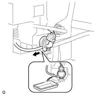
Remove the washer hose from the windshield washer motor and pump, and drain the washer fluid.
-
-
REMOVE WASHER INLET SUB-ASSEMBLY
-
Remove the bolt and washer inlet.
-
-
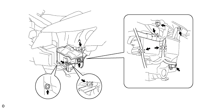
REMOVE WINDSHIELD WASHER JAR ASSEMBLY
-
Disconnect the 3 connectors and detach the 4 clamps.
-
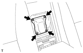
Remove the 3 bolts. Then detach guide A and remove the windshield washer jar and pump.
-
-
REMOVE NO. 3 COOL AIR INTAKE DUCT SUB-ASSEMBLY
-
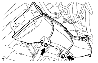
Detach the clamp, remove the 2 bolts.
-
Detach the 2 claws and remove the duct.
-
-
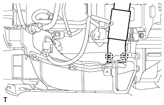
REMOVE INLET ENGINE ROOM ECM DUCT
-
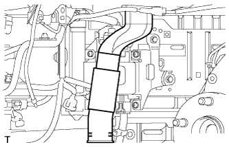
Remove the duct from the ECM box.
-
-
DISCONNECT FRONT ACTIVE STABILIZER CONTROL ACTUATOR CONNECTOR
-
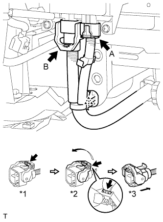
Disconnect the wire harness clamp.
-
Disconnect the actuator connector labeled A.
-
Disconnect the actuator connector labeled B.
-
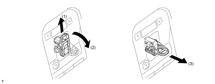
Release the lever's lock. (*1)
-
Press the claw and move the lever in the direction of the arrow in the illustration. (*2)
-
Disconnect the actuator connector. (*3)
Note
When disconnecting the actuator connector, do not apply excessive force to the wire harness.
-
-
-
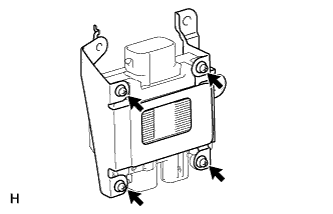
REMOVE FRONT ACTIVE STABILIZER CONTROL ECU
-
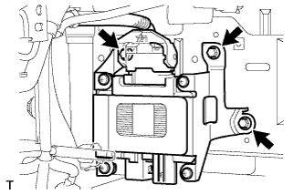
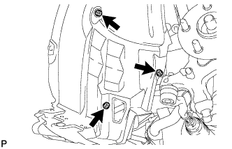
Remove the 3 bolts and ECU.
-
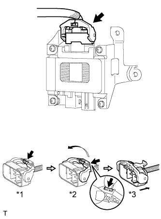
Disconnect the ECU connector.
-
Release the lever's lock. (*1)
-
Press the claw and move the lever in the direction of the arrow in the illustration. (*2)
-
Disconnect the ECU connector. (*3)
Note
When disconnecting the ECU connector, do not apply excessive force to the wire harness.
-
-
-
REMOVE BRACKET
-
Remove the 4 screws and bracket.
-