REAR SHOCK ABSORBER INSTALLATION

Tech Tips
-
Use the same procedures for the RH side and LH side.
-
The procedures listed below are for the LH side.
-
A bolt without a torque specification is shown in the standard bolt chart Click here.
-
INSTALL HEIGHT CONTROL VALVE O-RING
Tech Tips
It is unnecessary to perform the following procedures if the pneumatic cylinder with shock absorber has been replaced with a new one.
-
Apply a light coat of MP grease No. 2 to 2 new O-rings.
-
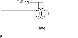
Install the 2 O-rings and a new plate to a height control tube or equivalent, as shown in the illustration.
Note
Set the plate between the 2 O-rings.
-
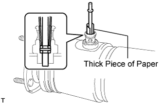
Insert the tube end with the 2 O-rings and plate into the pneumatic cylinder with shock absorber. Then, lightly push in the O-rings and plate with a thick piece of paper.
-
While holding the O-rings and plate in place with the paper, slowly pull out the tube.
-
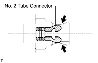
Install a new tube connector.
Note
Push in the tube connector until a "click" sound is heard.
-
-
TEMPORARILY INSTALL PNEUMATIC CYLINDER WITH REAR SHOCK ABSORBER ASSEMBLY LH
-
Install the rear shock absorber on the vehicle by installing the 3 nuts on the suspension support side.
- Torque:
- 64 N*m { 653 kgf*cm, 47 ft.*lbf }
-
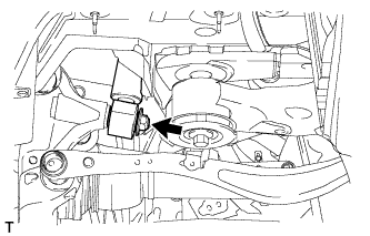
Temporarily install the lower side of the rear shock absorber on the rear axle carrier with the washer and a new nut.
-
Insert the height control tube into the pneumatic cylinder with shock absorber.
-
Pinch the connector No. 1 and set its tips into the groove of the shock absorber.
-
-
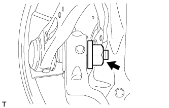
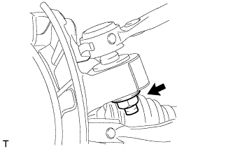
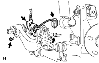
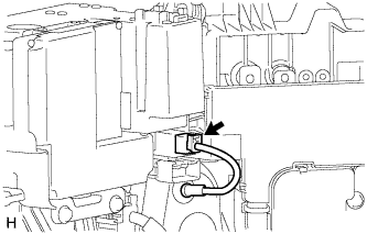
INSTALL ABSORBER CONTROL ACTUATOR
-
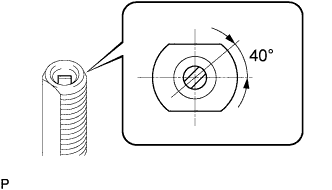
Check that the control rod of the rear shock absorber is in the position shown in the illustration.
Note
If the control rod is not in the position shown in the illustration, turn the control rod to adjust the position and install the absorber control actuator.
-
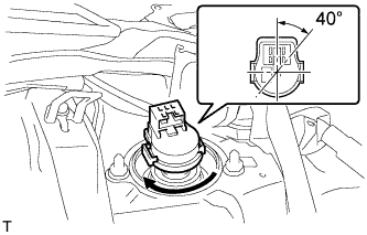
Install the absorber control actuator to the actuator support bracket.
-
Turn the actuator clockwise approximately 40° until a click is felt.
Note
-
Before turning the actuator, make sure to check that the actuator output shaft and control rod are securely connected.
-
Do not turn the actuator more than 40°.
-
Do not drop the absorber control actuator. If it is dropped, replace it with a new one.
-
-
-
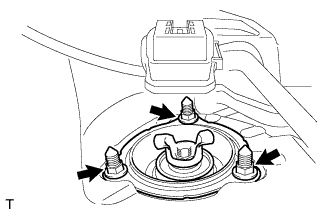
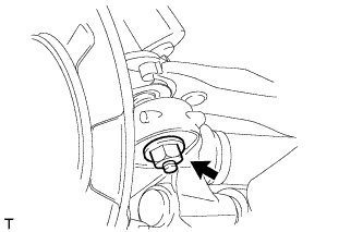
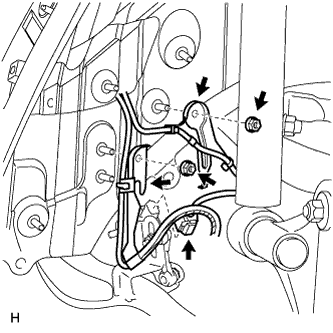
INSTALL REAR SHOCK ABSORBER CAP LH
-
Connect the connector to the absorber control actuator.
-
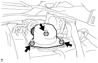
Install the absorber cap with the 3 nuts.
- Torque:
- 14 N*m { 143 kgf*cm, 10 ft.*lbf }
-
Connect the wire harness to the absorber cap.
-
-
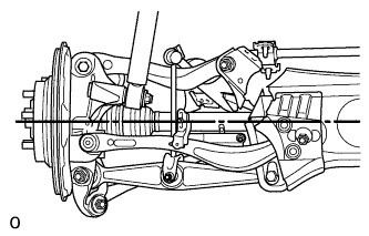
CONNECT TOE CONTROL LINK SUB-ASSEMBLY LH
-
Connect the control link with a new nut to the axle carrier.
- Torque:
- 118 N*m { 1203 kgf*cm, 87 ft.*lbf }
-
-
CONNECT REAR UPPER NO. 1 CONTROL ARM ASSEMBLY LH
-
Connect the control arm with a new nut to the axle carrier.
- Torque:
- 160 N*m { 1632 kgf*cm, 118 ft.*lbf }
-
-
CONNECT REAR UPPER NO. 2 CONTROL ARM ASSEMBLY LH
-
Connect the control arm with a new nut to the axle carrier.
- Torque:
- 160 N*m { 1632 kgf*cm, 118 ft.*lbf }
-
-
INSTALL REAR AXLE SHAFT NUT LH
-
Clean the threaded parts on the drive shaft and axle hub nut using a non-residue solvent.
Note
-
Be sure to perform this work for a new drive shaft.
-
Keep the threaded parts free of oil and foreign objects.
-
-
Using a 32 mm socket wrench, install a new rear axle shaft nut.
- Torque:
- 290 N*m { 2957 kgf*cm, 214 ft.*lbf }
Note
Do not stake the shaft nut.
Tech Tips
Stake the shaft nut after the axle hub bearing looseness and axle hub runout inspections.
-
-
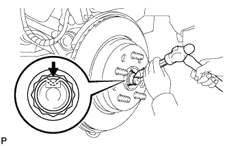
STAKE REAR AXLE SHAFT NUT LH
-
Using a chisel and a hammer, stake the axle shaft nut.
-
-
INSTALL LOAD SENSING VALVE SENSOR BRACKET
-
Install the bracket to the toe control link with the bolt.
-
-
INSTALL SKID CONTROL SENSOR WIRE
-
Connect the rear speed sensor connector.
-
Connect the pad wear indicator connector.
-
Install the sensor clamp with the bolt.
- Torque:
- 8.5 N*m { 87 kgf*cm, 75 in.*lbf }
Note
Do not twist the sensor wire when installing the clamps.
-
Install the 2 sensor clamps with the 2 nuts.
-
Connect the rear height control sensor connector.
-
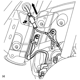
Insert the connector and grommet to the inside of the vehicle through the hole in the wheel house.
-
for RH:
-
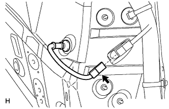
Connect the skid control sensor wire connector to the vehicle side connector.
-
-
for LH:
-
Connect the skid control sensor wire connector to the vehicle side connector.
-
-
-
INSTALL REAR WHEEL HOUSE LINER LH
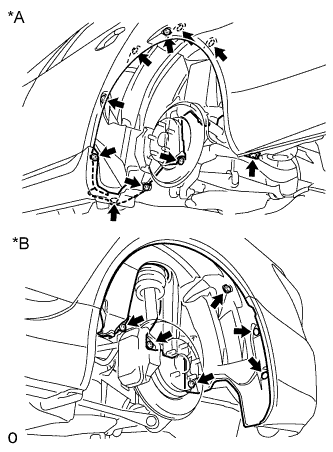
Text in Illustration *1 Front Side *2 Rear Side
-
Install the liner with the 3 screws, 11 nuts, 2 clips to the vehicle side.
-
-
INSTALL NO. 6 ROCKER PANEL MOULDING PROTECTOR
-
Install the No. 6 rocker panel moulding protector with the 2 clips and screw.
-
-
INSTALL PACKAGE TRAY TRIM PANEL ASSEMBLY
-
INSTALL REAR SEAT ASSEMBLY
-
for Power Seat:
-
for Ottoman:
-
for Fixed Seat Type:
-
-
STABILIZE SUSPENSION
-
Install the rear tires.
- Torque:
- 140 N*m { 1428 kgf*cm, 103 ft.*lbf }
-
Lower the vehicle and start the engine. Then fill the pneumatic cylinder assembly with rear shock absorber with air.
-
Lower the vehicle and bounce it up and down several times to stabilize the rear suspension.
-
Remove the rear tires.
-
Jack up the axle carrier with a wooden block between the jack and axle carrier. Apply a load to the suspension so that the rear drive shaft assembly is placed in a horizontal position.
-
-
TIGHTEN PNEUMATIC CYLINDER WITH REAR SHOCK ABSORBER ASSEMBLY LH
-
Tighten the nut on the axle carrier.
- Torque:
- 80 N*m { 816 kgf*cm, 59 ft.*lbf }
-
-
INSTALL REAR WHEEL
- Torque:
- 140 N*m { 1428 kgf*cm, 103 ft.*lbf }
-
CHECK CONNECTIONS OF TUBES FOR AIR LEAKAGE
-
Check the connection of the tubes for air leakage Click here.
-
-
CHECK SUSPENSION CONTROL SYSTEM
-
Check the suspension control system Click here.
-
-
INSPECT AND ADJUST REAR WHEEL ALIGNMENT
-
Inspect and adjust the rear wheel alignment Click here.
-
-
CHECK SPEED SENSOR SIGNAL
-
Check the speed sensor signal Click here.
-
-
ADJUST HEADLIGHT ASSEMBLY
-
Adjust the headlight Click here.
-
-
ADJUST OBJECT RECOGNITION CAMERA
-
Adjust the object recognition camera Click here.
-