REAR SHOCK ABSORBER REMOVAL

CAUTION:
Be sure to read the "PRECAUTION" thoroughly before servicing Click here.
Tech Tips
-
Use the same procedures for the RH side and LH side.
-
The procedures listed below are for the LH side.
-
REMOVE REAR WHEEL
-
REMOVE REAR SEAT ASSEMBLY
-
for Power Seat:
-
for Ottoman:
-
for Fixed Seat Type:
-
-
REMOVE PACKAGE TRAY TRIM PANEL ASSEMBLY
-
REMOVE NO. 6 ROCKER PANEL MOULDING PROTECTOR
-
Remove the 2 clips, screw and No. 6 rocker panel moulding protector.
-
-
REMOVE REAR WHEEL HOUSE LINER LH
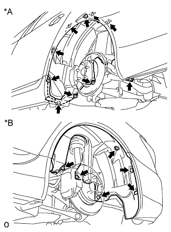
Text in Illustration *A Front Side *B Rear Side
-
Remove the 4 screws, 11 nuts and 2 clips from the liner.
-
-
REMOVE SKID CONTROL SENSOR WIRE
-
for RH:
-
Disconnect the sensor connector from the vehicle side connector.
-
-
for LH:
-
Disconnect the sensor connector from the vehicle side connector.
-
-
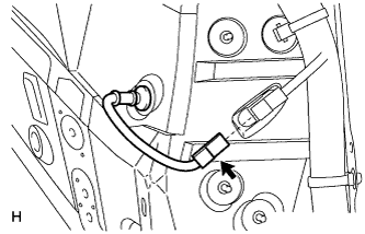
Disconnect the grommet of the speed sensor wire from the hole of the wheel house.
-
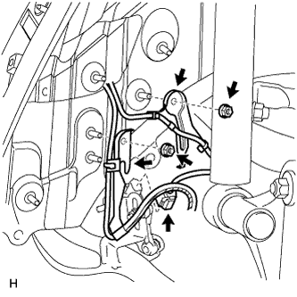
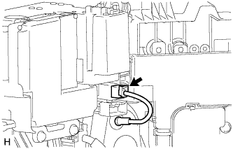
Disconnect the rear height control sensor connector.
-
Remove the 2 nuts and 2 sensor clamps.
-
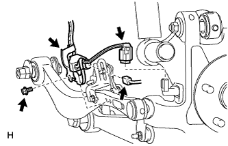
Disconnect the pad wear indicator connector.
-
Remove the bolt and sensor clamp.
-
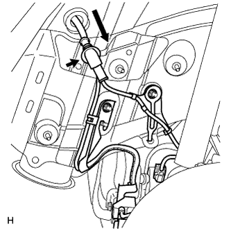
Disconnect the rear speed sensor connector.
Note
-
Be careful not to damage the speed sensor.
-
Prevent foreign matter from adhering to the speed sensor.
-
-
-
REMOVE LOAD SENSING VALVE SENSOR BRACKET
-
Remove the bolt and bracket from the toe control link.
-
-
DISCONNECT REAR UPPER NO. 2 CONTROL ARM ASSEMBLY LH
-
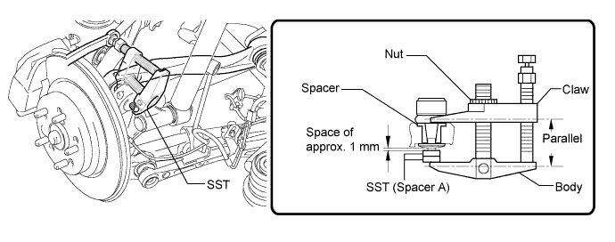
Remove the nut on the rear axle carrier side.
-
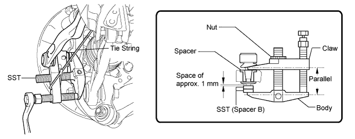
Install 2 spacers (SST spacer A) onto the rear upper No. 2 control arm so that there is a space of approximately 1 mm (0.0394 in.) between the arm and spacers.
- SST
- 09960-20010 ( 09961-02050 )
Note
-
Make sure to install the spacers (SST spacer A) as the steering knuckle spacer may shift.
-
As SST may become damaged, make sure the space between the arm and spacers is not less than 1 mm (0.0394 in.).
-
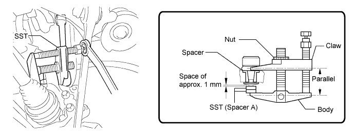
Using SST, disconnect the upper No. 2 control arm from the axle carrier.
- SST
- 09960-20010 ( 09961-02010 )
Note
-
Apply molybdenum grease to the threads and end of the SST bolt.
-
Do not damage the ball joint dust cover.
-
As the dust cover may be damaged, adjust SST with the center nut so that the body and claw are parallel.
-
Make sure to tie the string of SST to the vehicle to prevent SST from dropping.
-
-
DISCONNECT REAR UPPER NO. 1 CONTROL ARM ASSEMBLY LH
-
Remove the nut on the rear axle carrier side.
-
Install 2 spacers (SST spacer A) onto the rear upper No. 1 control arm so that there is a space of approximately 1 mm (0.0394 in.) between the arm and spacers.
- SST
- 09960-20010 ( 09961-02050 )
Note
-
Make sure to install the spacers (SST spacer A) as the steering knuckle spacer may shift.
-
As SST may become damaged, make sure the space between the arm and spacers is not less than 1 mm (0.0394 in.).
-
Using SST, disconnect the upper No. 1 control arm from the axle carrier.
- SST
- 09960-20010 ( 09961-02010 )
Note
-
Apply molybdenum grease to the threads and end of the SST bolt.
-
Do not damage the ball joint dust cover.
-
As the dust cover may be damaged, adjust SST with the center nut so that the body and claw are parallel.
-
Make sure to tie the string of SST to the vehicle to prevent SST from dropping.
-
-
DISCONNECT TOE CONTROL LINK SUB-ASSEMBLY LH
-
Remove the nut on the rear axle carrier side.
-
Install 2 spacers (SST spacer B) onto the toe control link so that there is a space of approximately 1 mm (0.0394 in.) between the arm and spacers.
- SST
- 09960-20010 ( 09961-02060 )
Note
-
Make sure to install the spacers (SST spacer B) as the steering knuckle spacer may shift.
-
As SST may become damaged, make sure the space between the arm and spacers is not less than 1 mm (0.0394 in.).
-
Using SST, disconnect the toe control link from the axle carrier.
- SST
- 09960-20010 ( 09961-02010 )
Note
-
Apply molybdenum grease to the threads and end of the SST bolt.
-
Do not damage the ball joint dust cover.
-
As the dust cover may be damaged, adjust SST with the center nut so that the body and claw are parallel.
-
Make sure to tie the string of SST to the vehicle to prevent SST from dropping.
-
-
REMOVE REAR AXLE SHAFT NUT LH
-
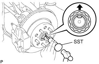
Using SST and a hammer, release the staked part of the rear axle shaft nut.
- SST
- 09930-00010
Note
Release the staked part of the nut completely, otherwise the screw of the drive shaft may be damaged.
-
While applying the brakes, remove the rear axle shaft nut.
-
-
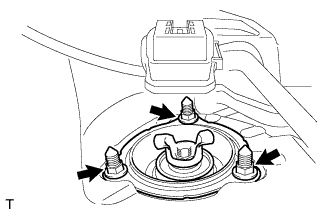
REMOVE REAR SHOCK ABSORBER CAP LH
-
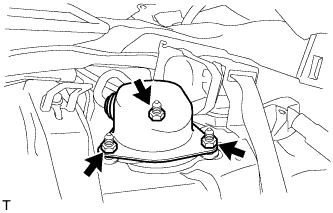
Remove the 3 nuts and shock absorber cap.
-
Disconnect the connector from the absorber control actuator.
-
Disconnect the absorber cap from the wire harness.
-
-
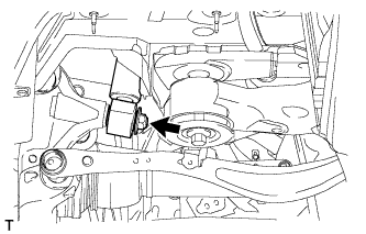
REMOVE ABSORBER CONTROL ACTUATOR
-
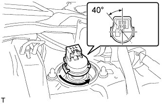
Turn the absorber control actuator counterclockwise approximately 40° to remove it.
Note
-
Do not turn the actuator more than 40°.
-
Do not drop the absorber control actuator. If it is dropped, replace it with a new one.
-
-
-
REMOVE PNEUMATIC CYLINDER WITH REAR SHOCK ABSORBER ASSEMBLY LH
-
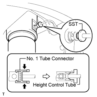
Pinch and pull the tube connector to release it.
-
Using SST, pull out the height control tube from the pneumatic cylinder with rear shock absorber. SST
- SST
- 09730-00010
Note
After pulling out the height control tube, replace the O-ring and plate with new ones.
-
Remove the 3 nuts on the upper side of the shock absorber.
-
Remove the nut from the lower side of the shock absorber.
-
Angle the axle carrier's upper tip toward the vehicle's outer side, and remove the shock absorber and washer.
-
-
REMOVE HEIGHT CONTROL VALVE O-RING
Tech Tips
It is unnecessary to perform the following procedures if the pneumatic cylinder with shock absorber has been replaced with a new one.
-
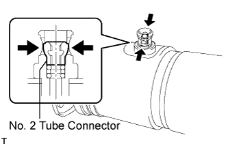
Using a screwdriver, detach the 2 clips and remove the tube connector.
-
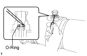
Using a screwdriver, remove the plate and 2 O-rings.
-