FRONT ACTIVE STABILIZER CONTROL ACTUATOR INSTALLATION

Tech Tips
A bolt without a torque specification is shown in the standard bolt chart Click here.
-
INSTALL FRONT NO. 1 STABILIZER BAR BUSH
-
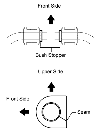
Install the 2 front No. 1 stabilizer bar bushes outside of the bush stoppers on the front active stabilizer control actuator as shown in the illustration.
Note
Make sure to face the front No. 1 stabilizer bar bush's seam to the lower rear of the vehicle.
-
-
TEMPORARILY INSTALL FRONT ACTIVE STABILIZER CONTROL ACTUATOR ASSEMBLY
-
Temporarily install the front active stabilizer control actuator and the front No. 1 stabilizer bracket LH and RH with the 4 bolts.
-
-
INSTALL FRONT NO. 1 STABILIZER BRACKET LH
-
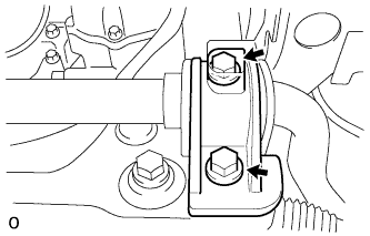
Install the front No. 1 stabilizer bracket LH with the 2 bolts.
- Torque:
- 115 N*m { 1173 kgf*cm, 85 ft.*lbf }
-
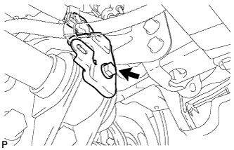
Install the wire harness bracket with the bolt.
- Torque:
- 22 N*m { 224 kgf*cm, 16 ft.*lbf }
-
-
INSTALL FRONT NO. 1 STABILIZER BRACKET RH
-
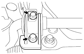
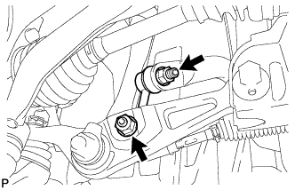
Install the front No. 1 stabilizer bracket RH with the 2 bolts.
- Torque:
- 115 N*m { 1173 kgf*cm, 85 ft.*lbf }
-
Install the water with motor and bracket pump assembly with the bolt.
- Torque:
- 22 N*m { 224 kgf*cm, 16 ft.*lbf }
-
-
CONNECT FRONT ACTIVE STABILIZER CONTROL ACTUATOR CONNECTOR
-
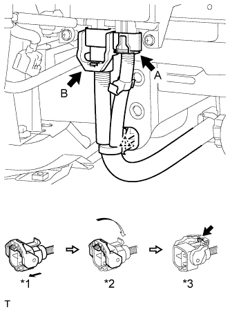
Connect the actuator connector labeled A.
-
Connect the actuator connector labeled B.
-
Connect the actuator connector. (*1)
-
Rotate the lever in the direction of the arrow until a "click" sound is heard. (*2)
-
Lock the lever's lock. (*3)
-
-
Connect the wire harness clamp.
-
-
INSTALL FRONT FENDER LINER LH
-
Position the grooves on the 2 pin hold clips vertically and insert the 2 clips to install them.
Note
Make sure that the groove on the pin hold clip is positioned vertically.
-
-
INSTALL FRONT FENDER WHEEL OPENING MOULDING LH
-
Attach the clip to install the moulding.
-
Install the 5 screws.
-
-
INSTALL FRONT STABILIZER LINK ASSEMBLY LH
-
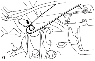
Install the front stabilizer link with the 2 nuts.
Tech Tips
If the ball joint turns together with the nut, use a 6 mm hexagon wrench to hold the stud bolt.
-
-
INSTALL FRONT STABILIZER LINK ASSEMBLY RH
Tech Tips
Install the RH side following the same procedures as the LH side.
-
INSTALL FRONT LOWER SUSPENSION MEMBER PROTECTOR
-

Install the front lower suspension member protector with the 9 bolts.
- Torque:
- for bolt A
- 20 N*m { 204 kgf*cm, 15 ft.*lbf }
- except bolt A
- 58 N*m { 593 kgf*cm, 43 ft.*lbf }
-
-
INSTALL NO. 1 ENGINE UNDER COVER
-
Install the No. 1 engine under cover with the 13 screws and 7 clips.
-
-
INSTALL FRONT WHEEL OPENING EXTENSION PAD LH
-
Install the front wheel opening extension pad LH with the 5 screws.
-
-
INSTALL FRONT WHEEL OPENING EXTENSION PAD RH
Tech Tips
Use the same procedure described for the LH side.
-
INSTALL NO. 2 ENGINE UNDER COVER
-
Install the No. 2 engine under cover with the 4 screws and 2 clips.
-
-
INSTALL FRONT CENTER FLOOR COVER
-
Install the front center floor cover with the 3 screws, 2 bolts and clip.
- Torque:
- 5.4 N*m { 55 kgf*cm, 48 in.*lbf }
-
-
CONNECT CABLE TO AUXILIARY BATTERY NEGATIVE TERMINAL
Note
When disconnecting the cable, some systems need to be initialized after the cable is reconnected Click here.
-
INSTALL BATTERY SERVICE HOLE COVER LH