FRONT ACTIVE STABILIZER CONTROL ACTUATOR REMOVAL

-
REMOVE BATTERY SERVICE HOLE COVER LH
-
PRECAUTION
Note
After turning the power switch off, waiting time may be required before disconnecting the cable from the auxiliary battery terminal. Therefore, make sure to read the disconnecting the cable from the auxiliary battery terminal notice before proceeding with work Click here.
-
DISCONNECT CABLE FROM AUXILIARY BATTERY NEGATIVE TERMINAL
Note
When disconnecting the cable, some systems need to be initialized after the cable is reconnected Click here.
-
REMOVE FRONT CENTER FLOOR COVER
-
Remove the 3 screws, 2 bolts, clip and front center floor cover.
-
-
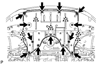
REMOVE NO. 2 ENGINE UNDER COVER
-
Remove the 4 screws, 2 clips and No. 2 engine under cover.
-
-
REMOVE FRONT WHEEL OPENING EXTENSION PAD LH
-
Remove the 5 screws and front wheel opening extension pad LH.
-
-
REMOVE FRONT WHEEL OPENING EXTENSION PAD RH
-
Remove the 5 screws and front wheel opening extension pad LH.
-
-
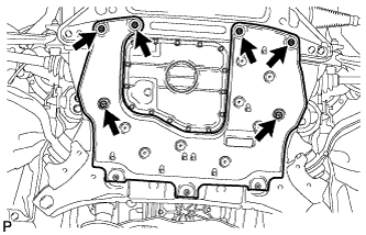
REMOVE NO. 1 ENGINE UNDER COVER
-
Remove the 13 screws, 7 clips and No. 1 engine under cover.
-
-
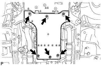
REMOVE FRONT LOWER SUSPENSION MEMBER PROTECTOR
-
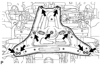
Remove the 9 bolts and front lower suspension member protector.
-
-
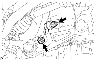
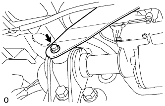
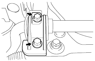
REMOVE FRONT STABILIZER LINK ASSEMBLY LH
-
Remove the 2 nuts and front stabilizer link.
Tech Tips
If the ball joint turns together with the nut, use a 6 mm hexagon wrench to hold the stud bolt.
-
-
REMOVE FRONT STABILIZER LINK ASSEMBLY RH
Tech Tips
Remove the RH side following the same procedures as the LH side.
-
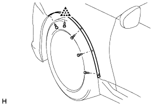
REMOVE FRONT FENDER WHEEL OPENING MOULDING LH
-
Remove the 5 screws.
-
Detach the clip and remove the moulding.
-
-
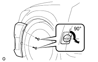
REMOVE FRONT FENDER LINER LH
-
Using a screwdriver, turn the 2 pin hold clips 90° and remove the 2 pin hold clips.
-
Partially remove the front fender liner LH.
Tech Tips
It is not necessary to fully remove the front fender liner. Partially remove it so that the bumper assembly can be removed later.
-
-
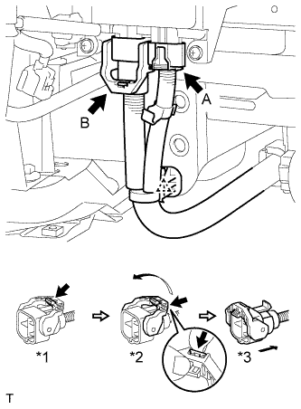
DISCONNECT FRONT ACTIVE STABILIZER CONTROL ACTUATOR CONNECTOR
-
Disconnect the wire harness clamp.
-
Disconnect the actuator connector labeled A.
-
Disconnect the actuator connector labeled B.
-
Release the lever's lock. (*1)
-
Press the claw and move the lever in the direction of the arrow in the illustration. (*2)
-
Disconnect the actuator connector. (*3)
Note
When disconnecting the actuator connector, do not apply excessive force to the wire harness.
-
-
-
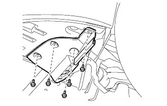
REMOVE FRONT NO. 1 STABILIZER BRACKET LH
-
Remove the bolt and wire harness bracket.
-
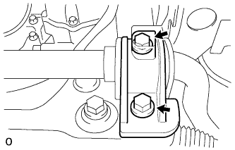
Remove the 2 bolts and front No. 1 stabilizer bracket LH from the front frame assembly.
-
-
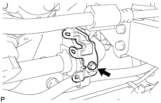
REMOVE FRONT NO. 1 STABILIZER BRACKET RH
-
Remove the bolts and disconnect water with motor and bracket pump bracket.
-
Remove the 2 bolts and front No. 1 stabilizer bracket RH from the front frame assembly.
-
-
REMOVE FRONT ACTIVE STABILIZER CONTROL ACTUATOR ASSEMBLY
-
Remove the front active stabilizer control actuator from the vehicle.
-
-
REMOVE FRONT NO. 1 STABILIZER BAR BUSH
-
Remove the 2 front No. 1 stabilizer bar bushes from the front active stabilizer control actuator.
-